The Engine Control Unit monitor project
By limpkin on Tuesday, January 11 2011, 20:34 - My Projects - Permalink
It has been quite a long time since I last posted a project on this blog... for the good reason that I am going to detail here for you guys!
So in this article you will see a quite complex project I have been working on for at least 6 months, which is an Engine Control Unit (ECU) monitor...

So... what is an Engine Control Unit (ECU)?
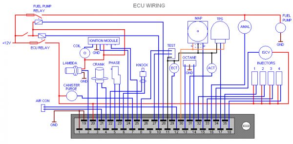
Well, basically the ECU is what controls your car. It is connected to sensors placed around your engine (air / engine coolant temperature, oil temperature, admission pressure, etc...) and outputs several signals such as the ones going to the ignition module, in charge of making the sparks inside your combustion engine :
Thus, by monitoring this ECU, you can have accurate readings about what is going on inside your car. The ECU monitor project I made here is meant to be used in previous generation cars, where all sensors and ECU outputs are analogic. Most recent cars currently use the OBD2 protocol usually implemented on a CAN bus. So why bother with previous generation cars? Well, firstly because it is easier to interface this project with them, and mostly because many owners of a specific car using this kind of ECU wanted an ECU monitor more up to date.
So, as you may have understood by now, I am currently selling this project to some people in many countries! Sorry guys, I will thus not give you all of the source code (10k lines of code!) here but however will give you everything else!
So... what do we want to measure that could be interesting?
Analog voltages :
- The manifold absolute pressure (MAP), which is the absolute pressure (relative to a vacuum) of the air in the intake manifold of an internal combustion engine
- The throttle position sensor (TPS), used to monitor the position of the throttle
- The engine coolant temperature (ECT)
- The air coolant temperature (ACT)
- Oil temperature
- Oil pressure
- Battery voltage
- Exaust gaz temperature (EGT)
Digital inputs :
- Car electrical system state: know if the car is used (power given to the ECU)
- Engine rotations per minute (RPM)
- RS232 bus to communicate with Air Fuel Ration (AFR) sensors
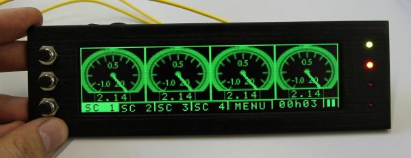
As you can see, this is quite a lot of inputs... that we want to display to the user. How? An LCD screen is obviously the best solution. Many of you readers know that most of the screens you see in everyday life have a very poor performance when exposed to direct sunlight. For this project, I found a 256 * 64 pixels OLED screen that is perfectly suited for this kind of application. OLED screens have the particularity to not have a backlight, each pixel producing its own light. Thus, contrast is perfect and colours pretty neat. The screen I am using is 15cm large by 5cm high, monochrome (16 levels of green)... which is again perfect for car use, to have a clear reading on the sensor values (who needs colour anyway?).
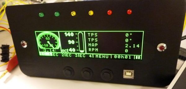
This picture shows the ECU monitor meant to be integrated in the central console of a car. The version you saw in the beginning is a DIN version, that can be placed in a standard car radio slot. As you can see, both of them have LEDS. Green / Orange / Red leds that are used to show the driver what his engine RPM approximately are, which is called a Shift Light. The other red leds are used as alarm leds. The ECU monitors also have 3 buttons in order for the driver to navigate through the user interface, and a USB connectivity for functionalities that I will detail later.
Obviously, this product (yes, I said product!) is used by car enthusiasts that tune their cars and try them on circuits. Thus, they wanted several features in their ECU monitor :
- several ways to display the sensor information (text with small & big fonts, graphical gauges)
- datalogging
- logs export to their computer
- easy graphical user interface
- choice for several types of sensors
Let's leave the software part aside, as it may not be that relevant to you. If you want, have a look at the video at the bottom of the page where all the functionalities are detailed. Let's focus on the hardware side :

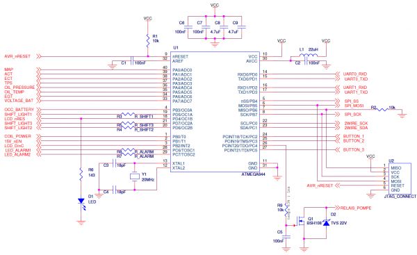
I chose an Atmega644 from atmel, in its DIP version. It was chosen because of its many inputs / ouputs that were corresponding to my needs and its big package allowing easy soldering. As you can see on the schematic, all its pin are used! I couldn't do better...
Some additional words on the hardware: to export the logs to the computer (and to upgrade the ECU monitor firmware!), I use an USB connection through the use of a standard FTDI RS232 to USB converter. For external RS232 communication with the AFR sensor, I am using a proper RS232 transceiver & transmitter that change the Atmega RS232 signal levels to levels that are specified by the RS232 protocol (usually +/- 10V). For data storage, I use I2C serial eeproms from Atmel. You may criticize this choice, as this solution is far from being the cheapest. However, as I had no other bus left on my Atmega , this was the only solution. In this ECU monitor, you can cascade up to 4 I2C serial eeproms of 1Mb each. For the parts numbers, please look at the bill of materials at the end of this article.
A few words on the LCD interfacing: it uses a SPI bus with an additional signal for data / command selection, it also uses 15 Volts to drive the OLED pixels (the voltage is thus produced by a step-up from Maxim) and 2.8 Volts for digital supply. As digital inputs must be 2.8V max, voltage bridges are used to reduce the Atmega ouput voltage levels (which is a very efficient & cheap solution as the communication is one way only).
So here is the PCB! Components have been deliberatly chosen big for easy soldering (0805 SMT components, through hole diodes). As this product will be used by people that may not be cautious with the wiring, all the analog inputs have been protected with operational amplifiers in 1:1 mode with protective diodes. To easily connect the ECU monitor with the ECU, terminals have been placed. The black panel has been made using rapid prototyping with plaster injected with cyanoacrylate. This solution has been chosen over ABS because of the raw finition of the latter, even if the panel made of plaster may break if you use the wrong screws to attach your pcb. The PCB is double sided, has big traces on one side and a huge ground plane on the other (no need to tell you why).
Again, I am very sorry to not be able to give you all the source code I made for this project. However, if you have any question or need bits of code to get started, I would be more than happy to help you. Please also consider this board as a potential development board, as it has loads of inputs / ouputs that most people need, a LCD screen, eeproms for data storage and USB connectivity! As I told earlier, I had to make 10k lines of code to produce a firmware that satisfies everybody. Luckily, I had two wonderful product beta testers during two months, that told me what they would like to have as well as the different bugs of the firmware (there weren't that many of them ;) ). If you ever plan on creating a product, I strongly advise you to do as I did: give your product to one or two testers that will test your project in all possible ways. And don't forget to put a bootloader protected by a password, in order to upgrade your firmware on your betatesters products! Iterative improvements such as the ones for this ECU monitor are very beneficial for you (to fully test your firmware) and for your customers (so they have everythings they want!).
Finally, here is the video of the final product :
You'll notice that I had access to a very good camera to shoot this video. You'll also see all the work needed to produce this firmware... almost all the 64k flash is filled.
Finally, here are all the files you will need to make this ECU monitor / development board:
The ECU monitor schematics The ECU monitor datasheets The ECU monitor production files The ECU monitor components OLED LCD Drivers Eeprom drivers
Here is also a similar project here, which is quite impressive.
A few words on the limitations of this ECU monitor:
- Obviously, it doesn't have a CAN bus connection. I might build a newer version integrating this connectivity. However, each car manufacturer has a different way to transmit the sensor informations over this bus!
- Maybe I should have addded a multiplexer on the analog inputs in order to implement the possibility to have more analog inputs in the future
- When the system is asleep, it still draws 20mA from the car battery. Well, it is not that much but if you are planning on leaving your car unused for more than 5 or 6 months...
- I am using a 5V voltage regulator to convert the 11-14V of the battery to 5v. It is not as efficient as a step-down but when voltage variations will occur on the 12v input, the 5v ouput will not be as affected as when using a step-down. Moreover, it can handle up to 18v analog input
Anyway, these are just small details, but I had to also write about the disavantadges of this design ;).
See you soon!


Comments
Looks amazing. Would you be interested in making a smaller, far more basic gauge for a particular car? We only need to display boost pressure, engine coolant temperature, RPM and time but over 2 smaller OLED screens.
The data would have to be collected off the LIN bus which is a 1 wire offshoot of the CAN bus.
Hey Man!
Well it depends for how many people... I am quite busy these days :).
Can you contact me to give me more info about this project?
Mat
Great project! definitly over my head.
Where can I source one of those OLED screens and do you think it would be possible to interface it with a arduino ? Thanks for showing us what is possible. How much are you selling these for?
Hey Marc,
Nothing is over your head... it is just a matter of spending some time to get all the aspects of the problem :).
You can get one screen on farnell (look for pmoled 5.5"). I think it would be possible to interface with arduino :).
Are you selling these as a kit? if so how much? I am trying to build a dashboard for my jeep using an arduino to read the sensors, firmata as the firmware and using flash on a laptop to display the data. I have that working but would rather have a system that is more rugged and self contained. If I buy seperate guages for my jeep they end up costing about $50 more or less each. Another idea I have is using arduino / bluetooth and android tablet?
@marc : I can sell you one assembled product if you want, and give you all the low level stuff so you can develop something on your own :). I'll send you an email. Concerning the arduino / bt solution, I don't know of existing solutions but i am sure that you could readapt some existing project found on the web :).
Really Amazing! Does it work in a 1996 Renault RT19?
(I am not sure whether you already got this, so I apologize for sending it twice)
@cwd :Well I don't think so... this has been made for another brand of vehicles :)
Hi, I am in the beginning stages of doing something similar and I stumbled across your build. I had a question involving the analog inputs. Are the sensors sent a consistent baseline voltage or does it fluctuate with the fluctuations of the car battery's voltage? I'm just worried about identical voltages meaning different values depending on VBatt and I am unsure how to remedy this if this is the case (The controller I'll probably be using does not have a VRef for it's analog ports)
@Nigel : You just have to be sure that your project's ground is exactly the same as the sensors'. Moreover, sensors are not directly connected to the car Vcc, but to 5V coming from the ECU :)
I have another question, this one's a bit noobish and probably a product of my DIY background. In each page of your schematics you have VCC flowing through a capacitor network to ground, I'm assuming I'm misreading this. Could you clarify for me? Thanks.
@Nigel : these are decoupling capacitors...
Hi,
that is a very nice Project. I'm searching a long time for such an Displayunit. But I want to use three MAX31855 for the ExhaustGasTemperature sensoring (pre Turbo 1,2 and one for the Catalytic). Further to oil temperature, pressure and MAP should be measured.
All other data are logged with my GREDDY Emanage.
Are there a possibility to get the source code?
Thanks for the nice Project
Best regards
@Denis Köllner : Sorry, I'm not planning to release it!
Hi.
I was looking for something like this and found your website.
I'm preparing a car (My car), with another engine but using the same wires inside.
But I wanted something like your project, to apply on it, since ECU is very limited to give values without a PC nearby.
I will put new sensors, different from the ones used by ECU and wanted something to make the reading and to show in LCD like yours.
Do you still work on this?
Thanks.
@Gaspar : I've actually stopped working on it... but if the hardware is roughly the same it should work as is :)