The FPSLIC matrix project
By limpkin on Wednesday, February 17 2010, 21:48 - My Projects - Permalink
So... here is the famous project I was telling you about!
I'm pretty excited to explain it to you as I have been working on it for quite some time now (mainly because of license problems regarding the FPSLIC System Designer software): the FPSLIC matrix project.
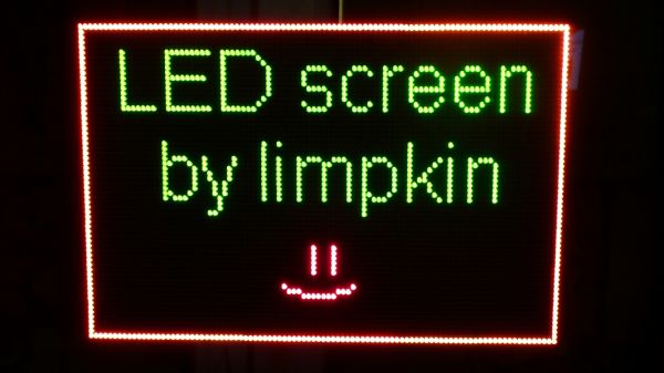
As many of you may have discovered, you can find on the internet plenty of small 8*8 led matrices whose dimensions are usually 1.25" * 1.25". These matrices can be mono-color (usually red or green), bi-color (red & green) or tri-color (red green & blue). As you may also know, you can find on the web plenty of projects using such matrices. So, why another project with leds? Well, mainly because I found this on ebay:
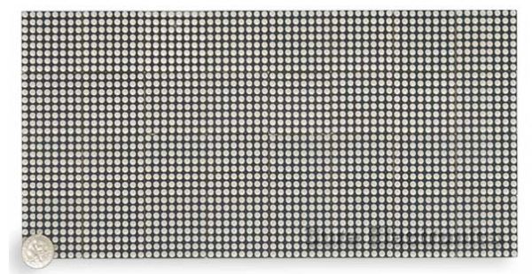
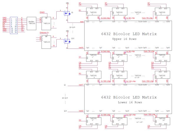
Yes.... a 5" by 10" bi-color led panel, with all the electronics included, pretty huge huh? This panel is actually an assembly of 8 * 4 * (8*8) led matrices, thus avoiding you the (very) annoying task of soldering every small matrix & electronic component on a big PCB. The whole system can be driven through a serial interface:
If you look closely at the schematics, you will see that you can't directly drive each led individually. The led panel is actually made of 64 * 32 bicolor leds (actually there are 2 leds in each spot) decomposed in 2 * 16 rows of 64 leds. Thus, you have to "scan" simultanuously each half of the panel, that is to say send the 2 * 64 (bicolor!) bits of the first row, then send the 2 * 64 bits of the second.... etc etc.
So... let's buy three of them! Why three? well, no particular reason, I think I wanted to build a 96 * 64 pixels screen to play pong on it ;).
I'm gonna address here a big controversy about the different ways to control such a panel. Here were (are) the different solutions at the time:
- Use a microcontroller (PIC / AVR / ARM / ...) with many IOs and drive the panel using c code.
- Use a FPGA and implement the scanning & other algorithms in VHDL
Or in a more distributed way, seperating the task of driving the panel (more suited for a FPGA based solutions) and the task of running the main program (more suited for uC based solutions):
- Use a FPGA & a microcontroller, interfaced to each other with some serial / parrallel bus
- Use a FPGA with an embedded processor (usually a NIOS...), allowing both components to access the same memory inside the same chip
- Use an ATMEL FPSLIC device, which is actually a component with a FPGA, a microcontroller (8 bits AVR) and some RAM inside a same chip.
I chose to go for the last solution as it was the best trade-off between the development tools, the soldering process (PLCC package), the price (free programmer, free c compiler...) and the time required to correctly handle every aspect of the whole system. In a FPSLIC, the AVR can directly communicate with the FPGA by a dedicated bus or indirectly using the shared SRAM memory. As you may have guessed by now, in this project, the FPGA will be in charge of driving the three LEDs panels and scanning the shared memory storing the picture to display. It will be also possible to integrate some part of the firmware in it (fade effects, rotations, shape effects...) in order to do less processing on the AVR side. Actually the FPSLIC is quite an old component, and i was unable to find a more up-to-date equivalent (which is a pity in my opinion). I won't go here into a lot of details concerning the different details of the FPSLIC device, but you are welcome to contact me.
So... how do we program such a device? Well, we actually program a small EEPROM memory with the configuration of the FPSLIC FPGA and the code of the AVR. When the FPSLIC will boot, the memory's contents will be automatically loaded into the device. The EEPROM memory's file is generated by the ATMEL programming utility which basicaly merges the FPGA configuration file with your compiled C program (.hex file) and some configuration bits.
How to program the eeprom? If you want to spend money, by buying the ATDH2200E or ATDH2225 programming cable. Or for free, by making your own cable based on the schematics of the latter ;).
Well, not everyone has a LPT port on his computer to program an EEPROM. We should clearly think of another solution... let's use a USB to serial converter. The FTDI232R is a great component for that task. This way, we could directly send our new firmware to our FPSLIC which would be in charge of reprogramming the eeprom (yes... that is tricky)
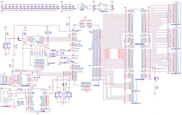
So here are the schematics of the board based on the constraints previously mentionned:
The board and the LED panels will be powered using 5V, but as the FPSLIC only accepts 3.3V we need to use a voltage regulator & buffers. Some words about the tricky part in this schematic: as you may have seen on the left side, a 6 pins micromatch connector is present to reconfigure the eeprom from your LPT port (mapping LPT > Micromatch: 2 > 1, 9 > 2, 10 > 3, ground > 4, ground > 5 & 6). The clock & data lines are multiplexed (U8) with some outputs of the AVR side of the FPSLIC. By default (if your LPT cable is not plugged and thus pin 4 is not grounded), the AVR will have access to the lines of the EEPROM memory. When you will plug your cable, the multiplexer will automatically allow you to reprogram your eeprom using the ATMEL CPS software. If you plan on re-using my schematics, I advise you to add an extra pullup on the RESET/nOE line of the EEPROM as the internal pull-up of the FPSLIC (I/O72) is not strong enough.
You can see on the bottom our USB connector & FT232R connected to the serial port of the AVR (PE0 and PE1). On the AVR side of the FPSLIC, for this package (PLCC) there is only one usable port (PE). So on this port will be connected our lines to reconfigure the EEPROM, 1 led, 2 buttons & the input/output lines from the FT232R. This way, we will be able at the same time to get the new firmware sent by USB while reprogramming the EEPROM. One button is present to do a system reset, 2 * 4 fpga lines are connected to 2 connectors (joysticks!) while the others are connected to the three LED panels. Here I chose to connect independent lines to each LED panel. The advantage of this choice is to be able to scan in a different way the LED matrices (to reverse an image for example) while its main inconvenient is to use more logic in the FPGA and to use more FPGA lines (well, we don't use all of them anyway). One independent LED can be driven from the FPGA side (very useful for debugging).
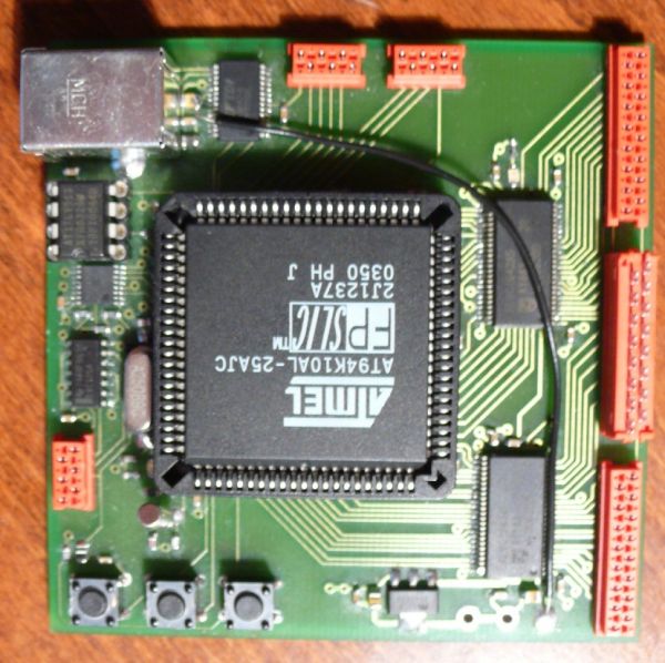
Here is the PCB:
You can see the three connectors on the right to connect to the LED panels, the USB port, the three buttons & the two joystick connectors. The board will be mounted behind the three led matrices.
Now that the board is produced and connected to the matrices, we have to think about how to program the whole system. Here, the FPGA will be in charge of scanning the two bitmaps (one for the red leds, one for the green leds) stored inside the SRAM memory while the AVR will run the main firmware which will listen to the commands given through USB and update the picture to be displayed. It may seem to you very simple but in reality it took me quite some time to implement it (just look at the vhdl code ;)). If you need some advanced details (I consider that it may not be very interesting to tell them here) just send me an email or leave a comment here. Well, after -I don't know how many- hours of programmation, here is the result!
I don't know if you are as impressed as me when I finaly got this "screen" working, so I'll try to put on this blog as soon as possible some videos of the LED matrix displaying animations (as I may bring it where I usually mix).
A few words about the serial communication: I use the Realterm terminal program, which basically dumps the EEPROM generated file through the serial link. No need to do operations on the file generated by ATMEL, you can send it directly as it is!
So what you have at the end here is a LED screen that can be connected to any computer through usb, which can be configured using the Serial port generated... isn't that great? More videos to come, stay tuned....
And as usual, here are the sources!
C code PCB files VHDL source Datasheets
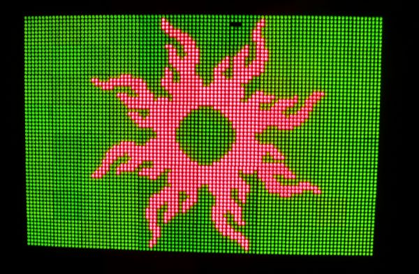
Edit: Here is another picture of the LCD panel displaying a 96 * 64 home made bitmap! Sorry for the quality of the picture, i'm not very good at manually tuning the camera parameters :). For info, to convert the picture from monochrome bitmap to C code, I used a 10 lines matlab script.

Comments
That's one HUGE display! Very cool!
I am working on a similar project, not as big but RGB using discrete 8x8 panels. Check it out if you like: http://www.forskningsavd.se/wiki/in...
There are videos in the "Coverage" section.
I was mainly going to do games, but I got stuck doing all sorts of other fun stuff so I havn't gotten around to writing Pong yet ;) Would be nice to hear more about what software ideas you've got brewing.
Thanks a lot stg!
I looked at your website... it is impressive how much time & effort you spent on it!
I think it is way more impressive that my project :), congratulations!
Hey man, every project is impressive in it's own right and using an FPSLIC was an absolutely brilliant idea!
You should drop by #forskningsavd on irc.freenode.org some day. I'm there mon-fri 9am-4pm CET.
Any chance getting ethernet running on your panel? A cross platform, cross country, networked led panel pong project would be a fucking awesome collaboration :D
Thanks for the FPSLIC comment STG. A lot of people who have gone with a FPGA & a softcore uC based solution.
I'll be there this afternoon then :)
About ethernet... originally this led panel was meant to be connected to a chumby, so everything is possible ;)
@Aaron : Thank you very much :) . Yes, the documentation is quasi non existent... that is really a pity! Actually I managed to know all there is to know on how to interface the control boards with them (have a look at the attached files). And if you have any question, don't hesitate to contact me! Cheers
@tobias : Hi Tobias!
I see you have a very good understanding of how the panels are working :) . I actually disable the led matrix before latching and re enable it after the latch and ABCD signals set.
I scan from the bottom to the top
@tobias :
I'm not sure that using state machines is really the way to go :) . At which frequency are you refreshing the display? I noticed that this ghosting effect increases with refresh freq.
@tobias : nice! glad you worked it out :)