RFID communication between 2 boxes
By limpkin on Wednesday, December 30 2009, 20:03 - My Projects - Permalink
Hey guys!
It has been quite a long time since I updated this blog. Sorry for that, and to make up for it I'll describe here the technical details of a project I made for Logitech. I'm sorry but I won't be able to talk about the final goal of this project as it has to stay confidential. However, you may not need to know everything as the principe of the system is quite simple: do some RFID communication between 2 boxes.
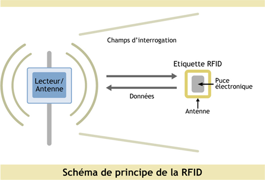
First, you need to know the basic principle of RFID communication. A RFID system is made of 2 components: one base station and one transponder. Both components have RLC circuits (tuned at the same resonance frequency) whose coils are put close to each other to enable communication. The base station's coil is powered while the transponder's is made to receive energy from the main coil. So how do we send/receive data? For the base station to send data, the main coil will be powered/unpowered depending on the bits to send. For the transponder to send data, it will change its resistance in the RLC circuit to vary the load applied on the main coil, thus allowing the base station to detect the voltage change on its terminals.
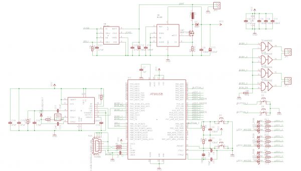
There are several frequencies allowed for RFID communication: 125kHz, 13.56MHz, 860-960MHz, 2.4GHz. This project is made using the 125kHz frequency. The two boxes use at90usb1287 microcontrollers from ATMEL (the same ones as in the Bluetooth project), are powered using 3.7V li-ion batteries (that can be recharged from the USB link using the MAX1811 from Maxim Instruments). On both schematics, you will see leds that show the data transfered from one box to the other. For the base station, the U2270B from ATMEL can directly drive the main coil and has input/ouputs to send/receive the data. However, it has to be powered from a 5V voltage source, thus involving the use of a step-up (the MAX608 from Maxim Instruments) to make 5V out of the 3.7V battery.
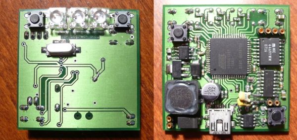
And the picture of the 5cm by 5cm PCB:

As usual, I won't go into details concerning these schematics, they are mainly based on the datasheets of each component. However if you have any question, don't hesitate to contact me! On these schematics you'll notice 2 buttons, 3 RGB leds, the main RFID RLC circuit and some logic gates....
Concerning the transponder, the U3280 is directly connected to the excited coil:
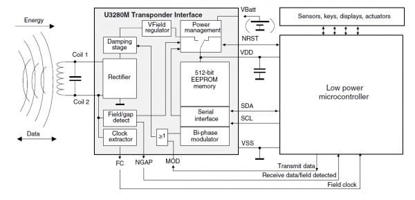
This little component can provide energy when its connected coil is being excited, and has of course inputs/ouputs to send/receive data. It can be powered using 3.3V voltage, so we will use here a 3.3V LDO voltage regulator:
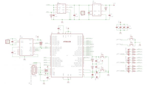
As in the base station, 2 buttons, 3 RGB leds...
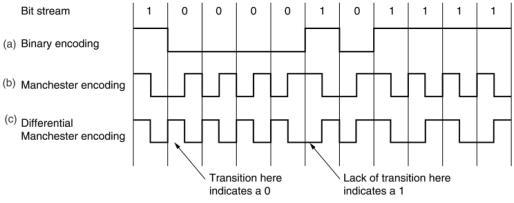
So, let's talk a bit more about the software part of this project. Firstly, I discovered a compatibility problem between the AT90USB1287 and the U3280 regarding the TWI interface allowing the uC to reconfigure the behavior of the transponder. Because of differences between the two components concerning the moment the data was sampled, i had to code a TWI bus controller. Secondly, as you can guess, sending data over the air is not trivial. If you go into the sources, you will see how I implemented the data transfers. To briefly resume, the transponder detects the magnetic field of the base station, send the data and waits for the confirmation that the data is correctly transfered. The data is sent using Manchester code (allowing the receiver to retrieve the clock used to transfer the bits), has a header of 8 bits indicating the beginning of the transmission and a 8 bits CRC tail for the receiver to verify the data it received.
 Each box is made to detect when the battery is charging and can be recognized as a HID device! As usual, here are all the sources, datasheets, eagle files, components listings if you want to make such project :).
RFID Components Listing RFID Source Code RFID PCB Files RFID Datasheets
