My new business card
By limpkin on Wednesday, October 3 2012, 17:57 - My Projects - Permalink
As it seems to be a new trend out there, I thought I would give it a go :-)
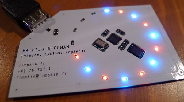
You may have seen that there are a couple of similar projects on the internet but most of them (in my opinion) are not very convenient.
What I mean by that is that they either require external batteries, or are too thick/not flat.
To me, a business card is meant to be stored in the wallet of the person you'll give it to. Therefore, it should be flat but also provide some super-ultra-funky functionalities ;-) .
As its main goal is to sell yourself, I thought that making the card a mass storage USB key containing a resume & pictures of produced work was a must... and why not add a couple of LEDs while we are at it?
The methodology
First, let's recap our requirements. The business card should:
- be flat
- provide USB connectivity
- have flash storage capability
- have a USB bootloader to program it
- have only low profile smd components
- be cheap to produce
Creating a cheap card usually involves dirty tricks that I will detail later.
As for being flat, I had an epiphany: stacking two PCBs, where the top one has holes to let the components go through.
And instead of using a USB connector, why not put traces on the PCB itself so it can directly plug in the computer?
That gives us another requirement: the stackup needs to be 2mm high. Therefore, we need to reduce a little the card dimensions so it can fit in a wallet. I chose to make it 50 by 80mm.
The components
I picked the AT90USB82/162 from Atmel as it is quite cheap but also because there are a few libraries available for it: Lufa and the teensy examples.
This microcontroller will be running at 8MHz, which is largely sufficient as the data transfers won't be huge :-) .
Just to be extra precautious, I also added an ESD protection chip especially meant for the USB lines. As for the flash, I took the M25PX16 from numonyx which is (only) 16Mb:
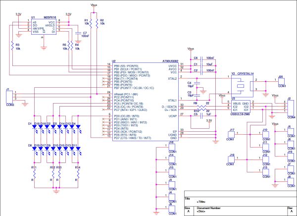
Don't pay attention to all the "CON1" connectors, as they are pads to connect the bottom PCB with the top one.
The AT90USB82 has an internal 3.3V regulator that I used to power the flash. Here is the dirty trick: as the flash only accepts 3.3v input voltages, I put resistors in series between the flash and uC so the internal flash protection diodes can lower the input voltage. Well, it's not for the price of the removed resistors (if I was doing a bridge), but more for the general aspect of the board.
And the AVR recognizes a high level at its inputs if the voltage is above 3V when powered at 5V... neat right?
Here is the bill of materials:

Total cost is a little under 5 dollars for a 100 units quantity, 4 if you remove the ESD protection chip. If you are curious about the BoM generation tool, have a look at my other post.
The bottom PCB
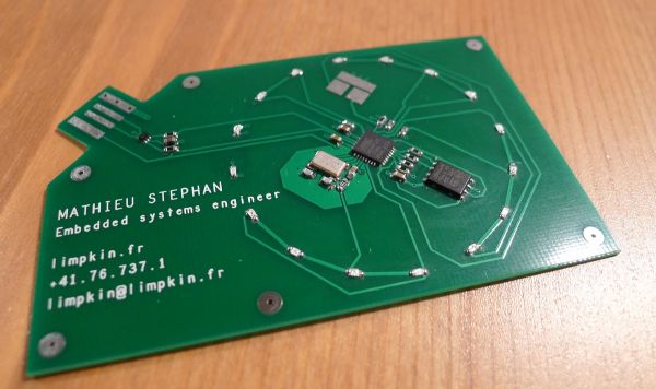
Yep, I tried to do some artistic routing ;-) .
Unfortunately, wanting low profile components usually involves fine pitch soldering, so I hope you are skilled in this matter!
You may have noticed the pads on the top of the PCB: by sliding a small piece of tin foil on these pins, it will make the AT90USB go into bootloader mode (reset and hwb pins).
As you only need to program the microcontroller once, it is not a problem if they are hidden in the stacking up process.
The firmware
Well, at the beginning of this project, I thought an AT90USB82 (8KB flash) would be enough to accommodate a USB mass storage stack but unfortunately I was wrong.
So I made two versions of the hardware (one with the 8KB AT90USB82, the other with the 16KB AT90USB162) and two versions of the software.
The small software version has a USB HID stack adapted from teensy code examples, while the bigger one provides the mass storage functionalities I talked about.
Why USB HID? Well, because now if you plug the card in your computer, it will input keyboard shortcuts to open a browser to go to my website. Ok, that may be considered a bit intrusive :-) .
Adapting the Teensy code to my needs was pretty straight forward (the pll setting just needed to be changed).
To handle all types of keyboard layouts, I'm entering the alt + xxx key codes to the computer.
LUFA & USB mass storage
Dealing with LUFA was quite tricky.
I'm personally using AVR studio 6, as I really like its new features (code completion, syntax highlighting). However, LUFA is exclusively meant to be used with make.
Therefore, it took me quite a while to learn which flags I needed to set for the compiler, as well as finding the .c files to include in the avr project (symbolic links).
Anyway, I did it in such a way that you only need to put the LUFA folder in the avr project one for the solution to compile. It'll then automatically look for the correct files in the LUFA folder.
LUFA, when using it with your own board, requires you to create the following files with given function names: Buttons.h / Dataflash.h / LEDs.h / Joystick.h (even if you don't have LEDs or a joystick).
As for the flash management, you'll need to edit DataflashManager.c & DataflashManager.h. I advise you to start from scratch when dealing with these files as the template code structure may not be the good one for you.
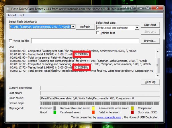
The maximum write speed I managed to attain was 38kB/s, and 225kB/s for the read speed. Far from great, but enough for a 2MB USB stick.
You'll need to learn about flash page sizes (the maximum amount of bytes you can write at once), flash erasable (sub)sector sizes (the minimum amount of pages you can erase in the flash) and OS block sizes (number of bytes the OS will consider as an undividable data unit).
Therefore, if your erasable (sub)sector size is bigger than your OS block size, you'll maybe need to do some buffering in your microcontroller: read the entire erasable sector, change the data you want and resend all the data to the flash.
Here comes a (very) dirty trick :-) .
The M25PX16 erasable subsector size is 4096bytes while its page size is 256bytes. By default, the LUFA OS block size is set to 512bytes.
In the template code, it is explicitely said that this value shouldn't be changed, as not all operating systems can handle a bigger block size value.
However, my AT90USB162 ram is only 512bytes so buffering was out of the question.
Only choice: set the OS block size equal to my flash subsector size, which is 4096bytes.
I got lucky and it worked... well for windows 7 / XP / Ubuntu 12 :-D , as I didn't try for the other operating systems.
Top PCB and stackup
Now that the firmware is done, it's time for the final assembly!
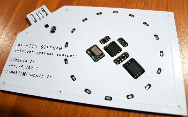
If you're using seeedstudio, you'll need to put the holes outlines in a .GML file. I made the mistake and the guys over there were kind enough to relaunch it into production.
The cut quality could be better... but the final result is quite neat:
The sources
If you appreciate this work and want to reproduce it, here are all the sources you'll need :-) :
Business card schematics Bill of Materials Bottom PCB gerbers Top PCB gerbers Teensy code LUFA final code
If you want me to assemble one for you, you can drop me a message ;-)
Cheers!

Comments
Hi.
Yes, I am interested in one of these cards. What do I have to do? :-)
As for your "dirty trick" - I don't understand why you need it. Why don't you use the internal regulator to provide the 3.3V power to the at90usb162 as well? For 8MHz this is totally within spec. I am unsure about the power needs of the flash, but 50mA should be plenty...
Thanks for an inspiring idea,
Simon
VERY COOL project, mate! I would LOVE for you to make one for me! What info would you put on it or would you just send me one of your own?
@Simon : Thanks! As a start, contact me on limpkin[at]limpkin.fr and we'll try to see if we can organize a group order :-) . As for the dirty trick, I decided to do so in order to reduce the number of LEDs in // with each other.
@KiwiSATX : Thanks! Please also send me an email on limpkin[at]limpkin.fr to join the group order
Great project! If you want to make this fit into an AT90USB82 or ATMEGA8U2, it looks like you're missing the -ffunction-sections and -Wl,--gc-sections options in the AS6 project file. You can find the first in the "Optimization" section of the C Compiler settings (first checkbox), while the second is in the Optimization section of the Linker options.
Without these options unused functions in the LUFA library won't be removed from the final binary. With it enabled, the compiled size is well under 8KB.
- Dean
@Dean Camera : Hi Dean! Thanks for having a look at the code. Actually even if the code was under 8KB I coulnd't fit it in the AT90USB82 as the bootloader takes 4KB of the flash... so the only way to make it fit would be to use ISP/JTAG (maybe use spring loaded pins?)
In the beginning of the project, I actually manually removed the unused functions to make it <8KB but then had this bad surprise
Are you making anymore of these cards?
@Erik : I'm affraid I'm not!