A Board to Parallel-Connect 4 High-Power Batteries
By limpkin on Sunday, May 26 2024, 14:52 - My Projects - Permalink
 ... if only it was as simple as connecting their terminals together!
Project Context
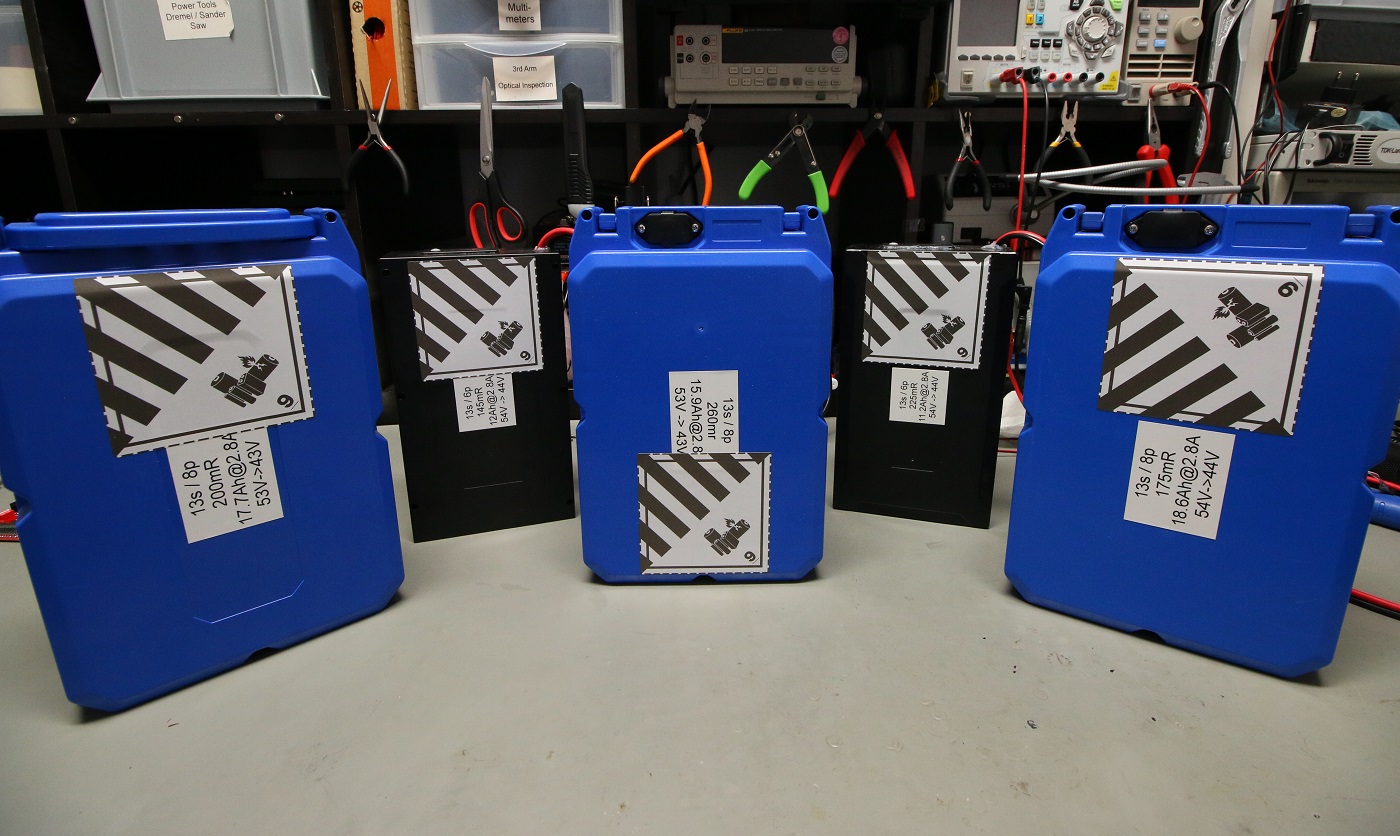
You may remember the custom 18650 cell-based battery I made a while back... well, I assembled more of them!
I therefore figured I should come up with a way of connecting several of them together in order to make a bigger "battery" out of them (because... why not?).
Before digging into this project, I should first mention that unless designing a dedicated circuit there's no way around matching the different battery voltages before connecting them together... the problems start after doing that.
Imagine the following scenario: you're (dis)charging your paralleled battery pack but for some reason one of the batteries disconnects from the pack (maybe its Battery Management System - BMS - detects an over-temperature condition and disables the battery). That scenario would be OK if the total current you were inputting/outputting was less than what your remaining batteries could handle, but what if it was not? Your remaining batteries would need to pick-up the slack, which could either go well (their respective BMS detect an over-current condition) or quite badly.
The selected architecture
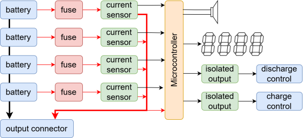
As you can see above, the board is based on current sensors to precisely know how much current is going in and out of a given battery.
A simple ATtiny microcontroller interfaces with them, together with a simple 7-segment based display, a buzzer and two isolated relays. The microcontroller therefore automatically detects the presence of a battery connected to a given connector by checking for current, and whenever a current reading drops to zero while the others don't then the MCU will enable the isolated relay connected the (dis)charge controller.
(Dis)charge controller you ask? A fancy word to say that most (for example) DC to AC inverters have dedicated disable inputs, which is exactly what we'll use in case an issue is detected.
Selecting the components
With the architecture nailed in, it was time to select the components going into this board:
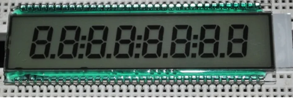
- TN display driver: the very same PCA8561 that was used in my doppler sensor
- hall-effect current sensor: the TMCS1108, Q3 version to sense up to +-11.25A
- 5V DC/DC: the SRH05S05 with its awesome 9V to 90V input range
- the MCU: the small ATTINY806 with its tiny 512B of RAM
- solid state relay: the small form factor CPC1017N
As you can see these are fairly straight-forward parts, leading to very simple schematics
Laying out the board
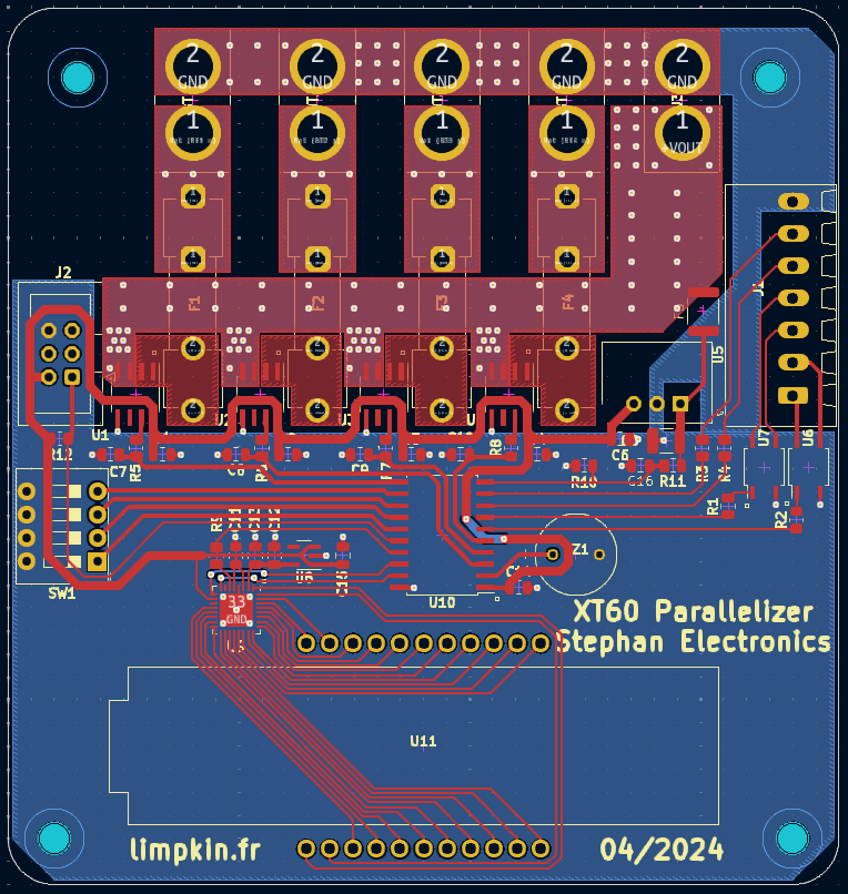
Layout was also fairly straight forward, but special attention was paid to maximize the distance between the "high" voltage and the other traces. As large currents may be involved, it was also important to have a single point ground connection with the battery connectors' ground.
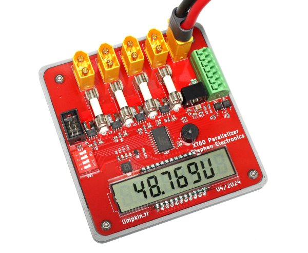
The Final Result

I'm quite happy with the look!
Copper was exposed on the high current traces to then add lots of solder to reduce ohmic losses. As you can also see, a mounting plate was 3D printed to prevent unintentional short-circuits that could lead to quite the fire.
A bit of bare-metal programming later, I had something ready for show time:
All the source files can be found here, thanks for reading!
