Assembling a 48V 18650 Cell-Based Battery
By limpkin on Sunday, November 26 2023, 12:48 - My Projects - Permalink
 ... without making any fire!
Project Context
This project isn't really a creation, but more like something I assembled together during the little spare time I could find.
It all started when I found a listing for 100x salvaged 18650 li-ion cells on a local auction website.
Not having a home to build a powerwall into, I thought of the next best thing to do with them: make my own 48V backup battery. Why buy a new (and certified) battery when a geek can make one and potentially burn his/her appartment in the process?
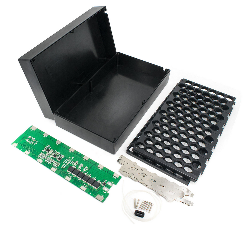
The Battery Kit
 I then started looking on the interwebs for similar projects... and videos of lithium fires.
I was quite surprised when I stumbled upon a (chinese) 48V 30A DYI battery kit on ebay for less than $40!
This kit seemed to be made for e-bikes and came with 18650 holders, a Battery Management System (BMS) and the box that goes around them. All that was then needed was the 18650 cells, a spot welder, (very) thick wires and a high current connector.
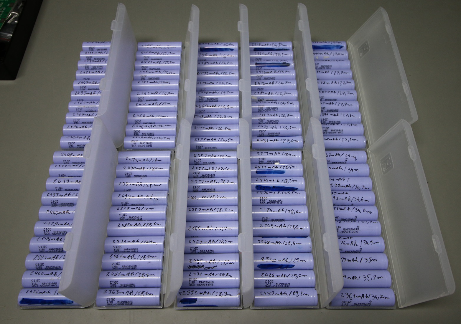
Cleaning out the Cells
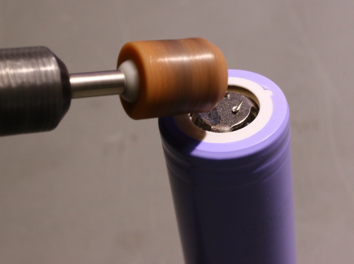
The salvaged cells I purchased locally still had pieces of nickel strips on them. I therefore used a dremel and the grinding bit you see above to clean the 18650s.
I then used lithium cells chargers to measure every 18650 cell capacity. All cells (surprisingly) had a capacity between 2300mAh and 2600mAh, but I found these measurements to not particularly be repeatable.
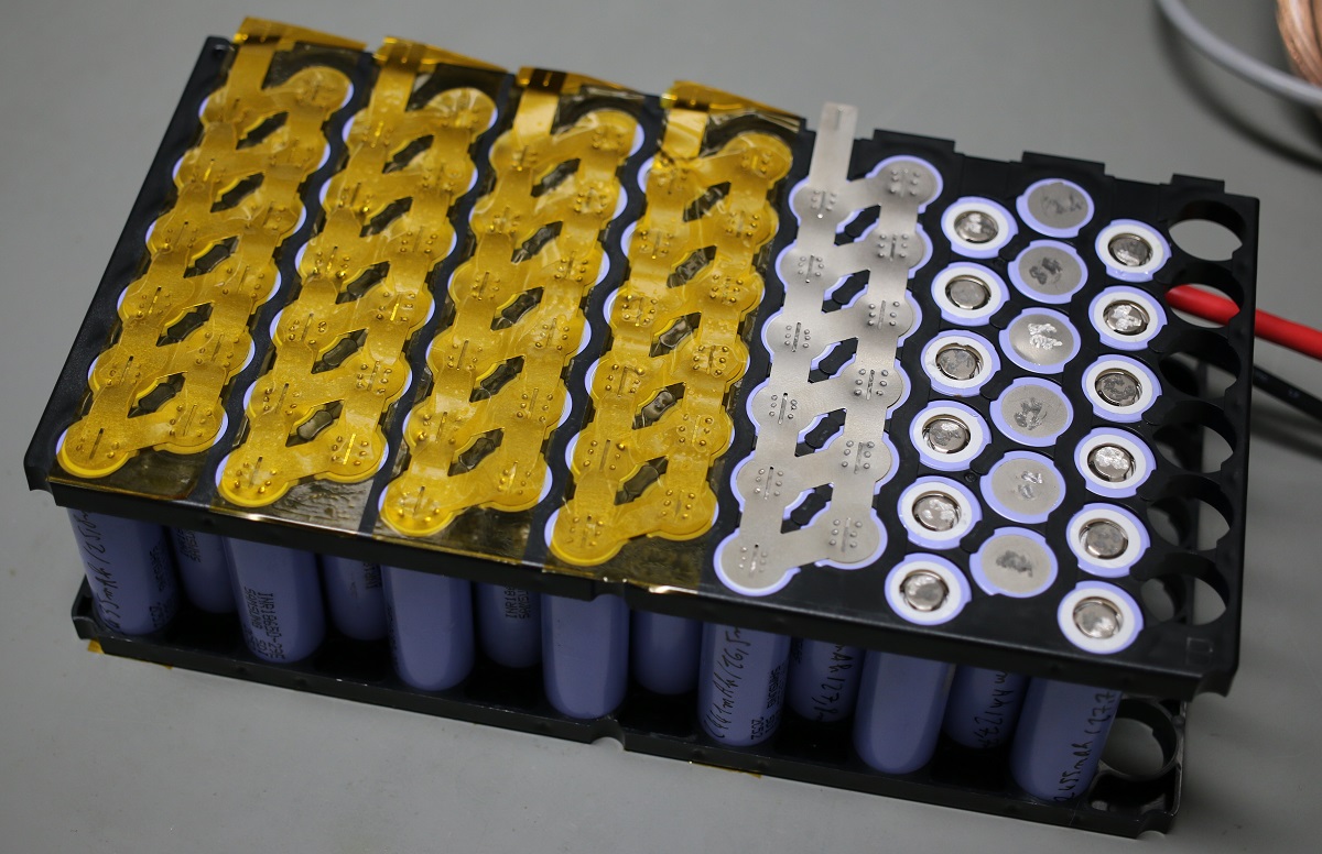
Balancing out the Cells
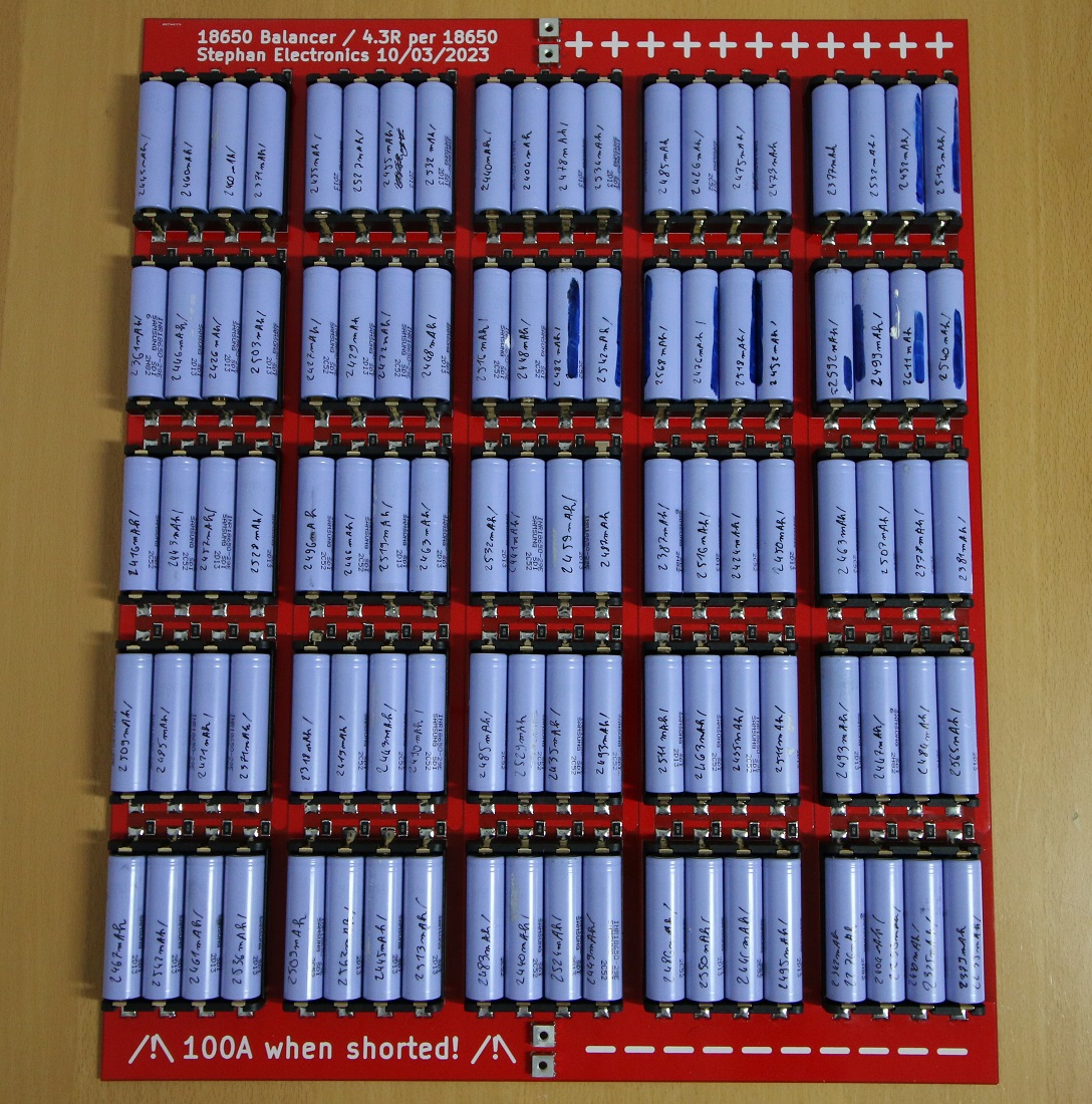
The idea of assembling a battery with 78 fully charged lithium cells wasn't particularly appealing to me. I therefore designed the gigantic PCB you see above, which essentially puts all cells with series resistors in parrallel.
The goal of this contraption is therefore to balance all the cells (so I don't connect a 3.6V cell to a 4.2V one during assembly) and discharge them all to a safer voltage before assembly (using an external programmable load).
Here's the thing though: every PCB manufacturer you'll find out there won't (for some reason) sell you a single PCB: the minimum order quantity is 5. But PCBWay came to the rescue and graciously offered to produce them for me!
I found the 18650 cell holders on aliexpress and soldered them together with the balancing resistors... which took quite a while. Once the board was assembled and the cells balanced, I then took the opportunity to measure each cell series resistance with an ESR meter. That was the result:
This much more reliable measurement painted a clearer picture of the cells' states. Interestingly, it did look like the higher the measured the ESR, the more capacity was remaining. I'm guessing this is due to the fact that for a random cell distribution a battery pack, the cells with the lower ESR would contribute more current than the others. That or something is up with my cell charger.
Soldering the Wires
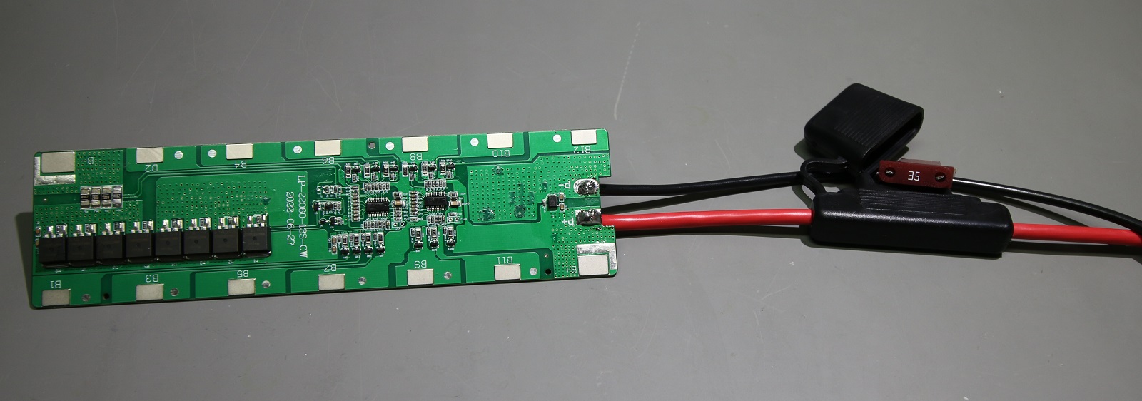
For obvious cost reaons the BMS didn't come with wires, so the first step before spot-welding the cells was to solder some thick gage wires I bought from Digikey. As you can see above, I even added a (very big) fuse assembly as an extra precaution.
Assembling the Battery
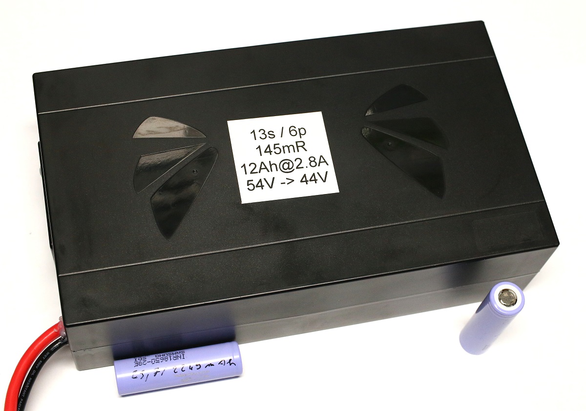
This obviously was the most dangerous part of this adventure as this pack is composed of 13 times 6 parallel cells in series (aka 13s/6p). When selecting the groups of 6 parallel cells, I picked the cells with similar internal resistance so no cell would work harder than another. I double checked that all cell voltages were equal and then interleaved groups of 6 cells with low and high ESR to make sure that one side of the battery wouldn't get hotter than the other during charge/discharge.
Before spot welding the last group of 6 cells to the BMS most positive tab, I tested the BMS using a lab power supply to simulate a group of 6 cells' voltage. When performing a battery discharge using an external programmable load, I set a simulated cell voltage of 2.8V and checked that the BMS would stop the discharge. Similarly, when performing a battery charge I set a simulated cell voltage of 4.2V and checked the BMS would stop the charge.
Finally, I discovered holes on the BMS to solder a thermistor. As I had a few in stock, I soldered one and also did check that the BMS would stop the discharge when the sensed temperature would get above 60degrees.
A Final Precaution
To really make sure the battery wouldn't overheat, I found a temperature sensor with an alarm feature.
I obviously tested it before adding it into the assembly.
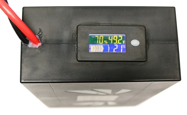
The Final Result
Here it is!
I performed a discharge/charge test and measured that the battery had a 570Wh capacity and a 145mR internal resistance... not bad!

Comments
Nice! I have a non functional ego mower battery pack that won't charge anymore, it probably has only one or two bad cells, and the BMS and charger display a fault code. I'm hoping to get it going again and maybe starting a little side hustle rebuilding them. I also want to do my own E-bike packs. I would go about testing/balancing the cells at more like 10 at a time, rather than 100. But still great info. Thanks
Why there's only one comment ahead of me is unfathomable..
Dude...
Spot-on job with the documentation alone!
Never-you-mind that the pack appears better in build (And SAFETY!) than 99% of commercial offerings.
You knocked that one out the park, Sir..
Keep up the Excellent work!
Here's to seeing what you come up with next, Cheers!
thanks a lot for the kind words Daymon!