A Board for Current-Based Side Channel Attacks
By limpkin on Tuesday, November 14 2023, 22:15 - My Projects - Permalink
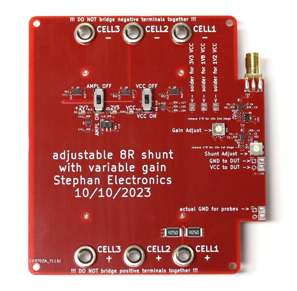 Or how to snoop on targets by looking at their current consumption...
Introduction
For several months, I had the chance to share an office with a security researcher whose hobby was to break the ESP32 AES engine by only looking at its current consumption.
His measurement setup was not ideal: long wires, a noisy current probe that required lots of trace averaging to measure anything... something needed to be done!
Selected approach

Before we begin, it's important to know that the tiny bit of leakage current that gives you tips about what data the AES encryption engine is currently dealing with is buried inside the overall current measurement.
This effectively means that special attention must be paid to noise, or in other words the measurement setup you use shouldn't introduce (lots of) additional noise before the signal digitization performed by your oscilloscope.
And unfortunately for us, the typical ways to measure current at high frequencies (differential & current probes, LISNs) were indeed found to add so much noise that a side channel attack wouldn't be feasible.
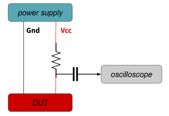 You may now be wondering why I didn't mention the simplest current measurement technique of all: the shunt resistor (shown above). Just put a resistor in line with your power supply, put your probe across it and voila, right?
Unfortunately, this measurement technique doesn't offer enough gain and is prone to ground loops: to precisely measure low currents, you'd need such a high resistor value that your target wouldn't boot in the first place.
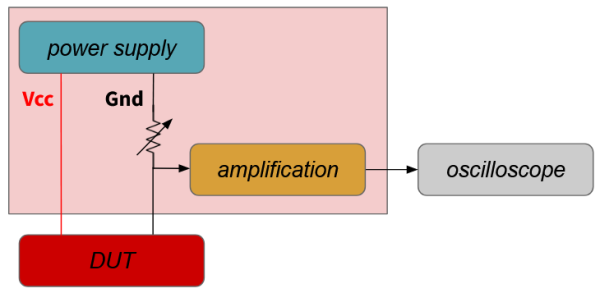
So what about a "standalone" amplified shunt resistor: a small value resistor, followed by low-noise amplifiers?
Coming up with requirements

How to come up with requirements when you don't know what signal you're looking for?
I looked at the different measurement tools above and came up with the following specifications:
- shunt resistor value: reasonably low, between 1R and 10R
- gain: tough one... around 100x, adjustable?
- frequency: let's aim for 1 to 500MHz
- noise: as low as possible, obviously!
- battery powered
I wanted to design something as versatile as possible to increase the odds that I wouldn't need to do a complete redesign.
Why battery powered you may ask? Well, standalone power supplies are noisy.
As measurement sessions typically last hours, 18650 batteries seemed like the obvious choice.
Amplification chain schematics

From left to right you can see:
A 10R potentiometer followed by a high pass filter: this allows the user to manually adjust the low side shunt resistance. It's important to note that the potentiometer doesn't really behave like a potentiometer above 20MHz or so. Testing revealed this wasn't a big issue as low frequency contents are way more present in current measurements, so they're the ones that need to be attenuated the most. The following high pass filter is only here because leakage information is always above 2-3MHz.... and if you'd amplify DC then your output would quickly be saturated!
A first stage amplifier: the OPA855 was selected for its impressive specs: 8GHz gain-bandwidth product and a <1nV/sq(Hz) input voltage noise rating! By default configured for a x19 gain / 421MHz BW, removing a 50R resistor changes the gain to x10 and allows a 800MHz BW.
An adjustable 25dB attenuator: specified from DC to 2.5GHz, it "only" needs a negative input between -3V and GND to vary the applied attenuation.
A second stage amplifier, identical to the first stage one.
Just looking at the amplifiers and attenuator, high-Z loaded, the overall amplification chain gain can be set between 6.8 and 120,6. To get the current to voltage amplification value, you then need to multiply these last 2 values by the set potentiometer value.
The three drawbacks that don't matter (much)
First drawback: the potentiometer and selected attenuator have different characteristics at different frequencies.
This means that the circuit gain across frequencies won't be flat... which is fine! Side channel measurements are differential measurements that look for amplitude variations for different input data.
Second drawback: the output may saturate.
As previously mentioned we may be looking for small buried signals, so if the gain is set too high then some input signal frequencies may lead to output saturation. Testing revealed that this was also fine as relevant leakage seems to be present during "quiet times". Moreover, the OPA855 has a <5ns recovery time specified.
Third drawback: the target ground isn't your measurement setup ground anymore.
This is obviously due to the shunt resistor that essentially "lifts" your DUT ground to a couple mVs. This may be something to keep in mind when designing your measurement setup: your oscilloscope input grounds are connected together so if you were to connect another oscilloscope input ground to your DUT ground then your shunt resistor would essentially be shorted. That's the theory though... in practice the ground voltage difference is so low that I didn't see any impact when doing so. Moreover, the measurement board does include some solder pads/pins to offer real ground connection.
The power supplies
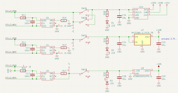
I'm really not a big fan of designing devices that use 18650 li-ion batteries.... but no choice.
This project uses four batteries:
- two to provide the +-2.5V(ish) voltage rails required by the op-amps and attenuator
- two in (kinda) parallel to provide power to an LDO with three outputs
Why that last LDO? To provide a clean power supply to the target as an external one would just add more noise to our measurements. Finally, protection circuits are present on the board to protect the 18650 cells from over charge and over discharge.
Measuring the transfer function
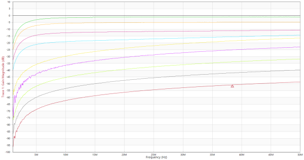
Using my bode100 with 20dB of external attenuation and a 45R series resistor I then injected current between the DUT ground and the actual ground to measure the above transfer function, for different shunt resistance and different set attenuation values.
It's in my opinion quite impressive to measure such a wide attenuation range of nearly 50dB.
In that wiring configuration, assuming 50R is presented to the bode100, we'd expect a theoretical maximum gain of:
20log10( (8.33/50) * 19 * 19) - 6dB - 3.6dB - 6dB - 20dB = 0dB... nearly exactly what is measured.
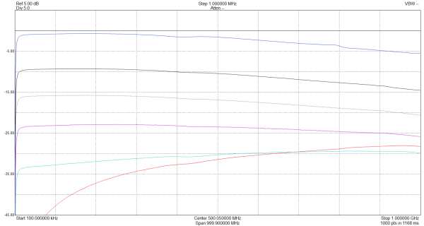
Measuring between DC and 1GHz, I was quite impressed by seeing such a flat frequency response.
Does it work? The conclusion

It does, so well that I actually was invited to hardwear.io to talk about it:
The board is currently being used by several security researchers out there and ICs have already been broken with it!
You may find its source files here, the board is available for sale here: EU store / US store.
