A Small Line Injector to Measure PSRR
By limpkin on Wednesday, February 21 2024, 15:39 - My Projects - Permalink
 so many measurements now made possible!
Project Context
Have you ever wondered how well a given component (voltage regulator, operational amplifier, ferrite...) could filter the noise coming out of your power supply?
In theory all of these components' datasheets should provide you with a figure of merit, typically the Power Supply Rejection Ratio (PSRR). But what tool should you use to make sure reality matches theory?
Answer: a Line Injector.
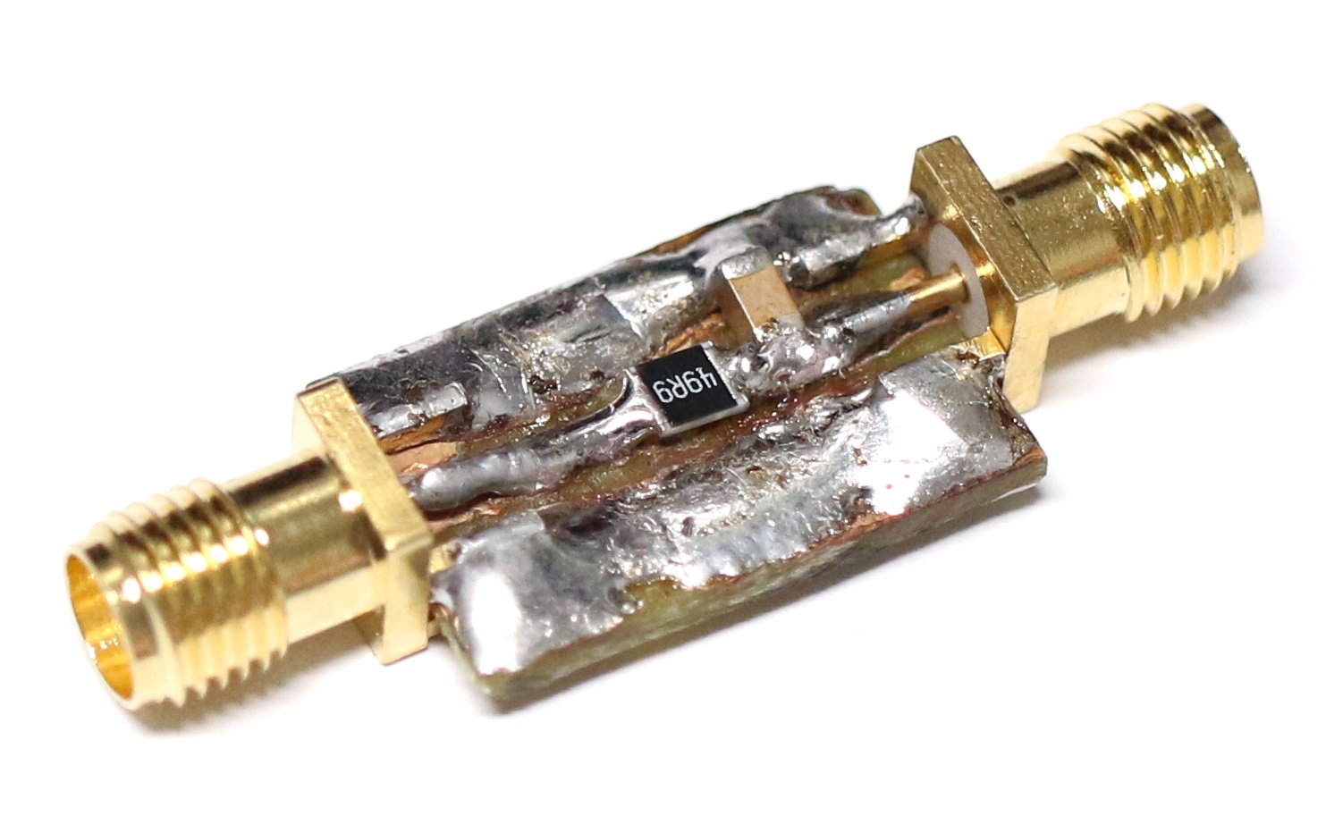
What's a Line Injector?
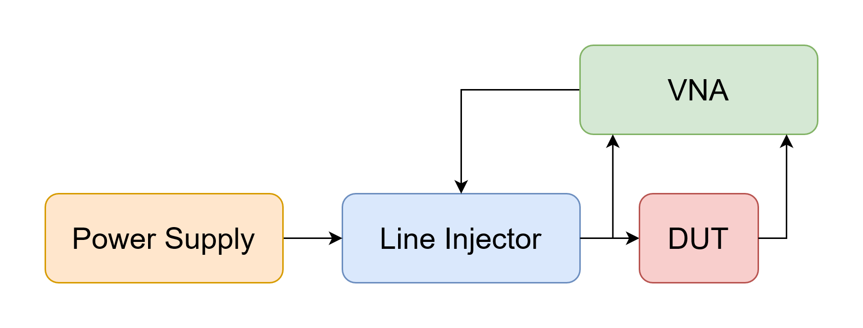
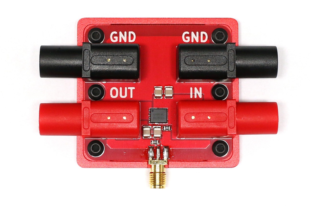
A line injector is a relatively small device that is inserted inline with your power supply lines to inject any kind of perturbation signal.
By measuring the perturbation signal before and after your Device Under Test (DUT) you can then deduce how good the DUT is at filtering out unwanted noise at different frequencies. You may find some interesting application notes on PSRR measurement here, here and here.
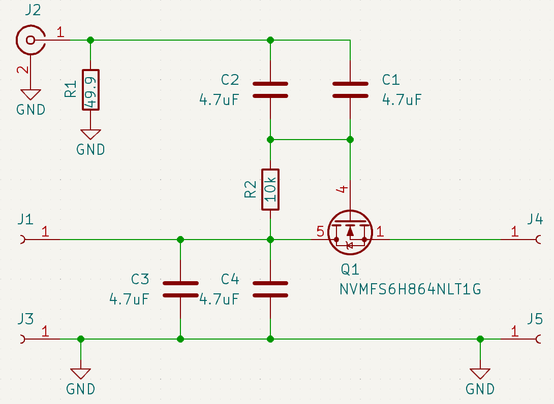
As you can see from the above schematics, it is fairly simple to build too!
It essentially consists of an N mosfet transistor (Q1) that is biased by R2 to let the current pass to the line injector output. Q1's gate is AC-coupled to the SMA modulation input port so that the modulation signal can remain centered around 0V.
The NVMFS6H864NLT1G mosfet was selected for its relatively low gate threshold voltage (1.2V to 2V), relatively high drain to source maximum voltage (80V) and low junction-to-case thermal resistance (4.6deg/W).
However, the main (but not so important) disadvantage of such a design therefore is the presence of a voltage drop between the line injector input and output terminals, equal to the N-Mosfet threshold voltage for a given current.
This has 2 main consequences:
- the output voltage needs to be measured when aiming for a given supply voltage at the DUT
- the more current passing through the line injector, the more power is dissipated by Q1
Designing the case
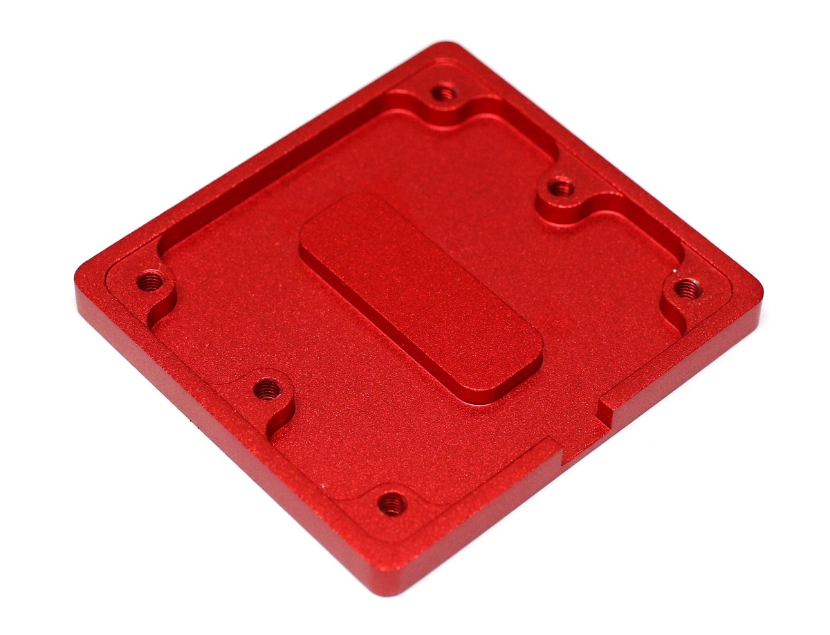
To mitigate the potential heat dissipation issue, I designed the above metal plate to take the heat out of the mosfet from the bottom of the 0.8mm thick PCB.
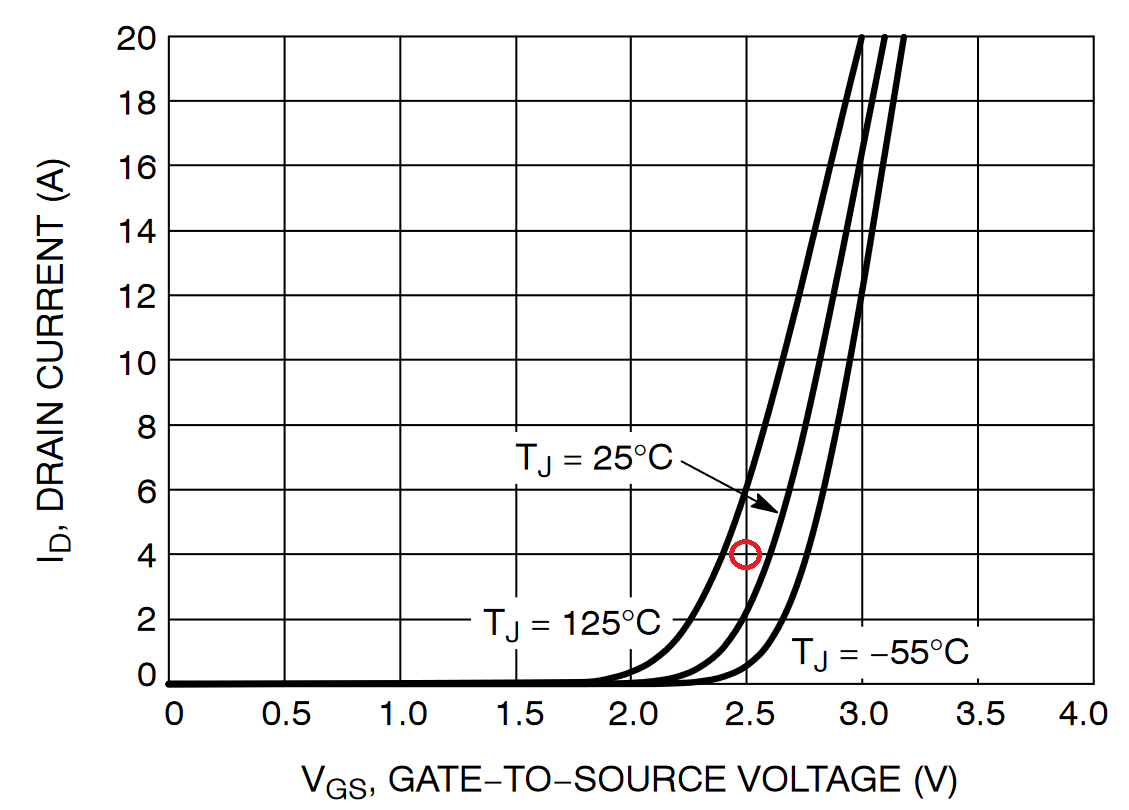
The next step was to stress test the whole assembly at the maximum current I was planning to use the line injector at.
I aimed for 4A, which for a measured 2.46V voltage drop at steady state means a ~10W power dissipation.
I used a power supply and a programmable load, put the assembly on its side to better expose the aluminum to the air and let everything reach its steady state temperature.
Result: a case temperature of 88 degrees (!), a mosfet temperature of 111 degrees which I guess is exactly the junction temperature if you look at the diagram below (remember that the gate is connected to the drain through 10k):
If one was to put that line injector on top of another heat sink then one may use it for a lot more than 4A!
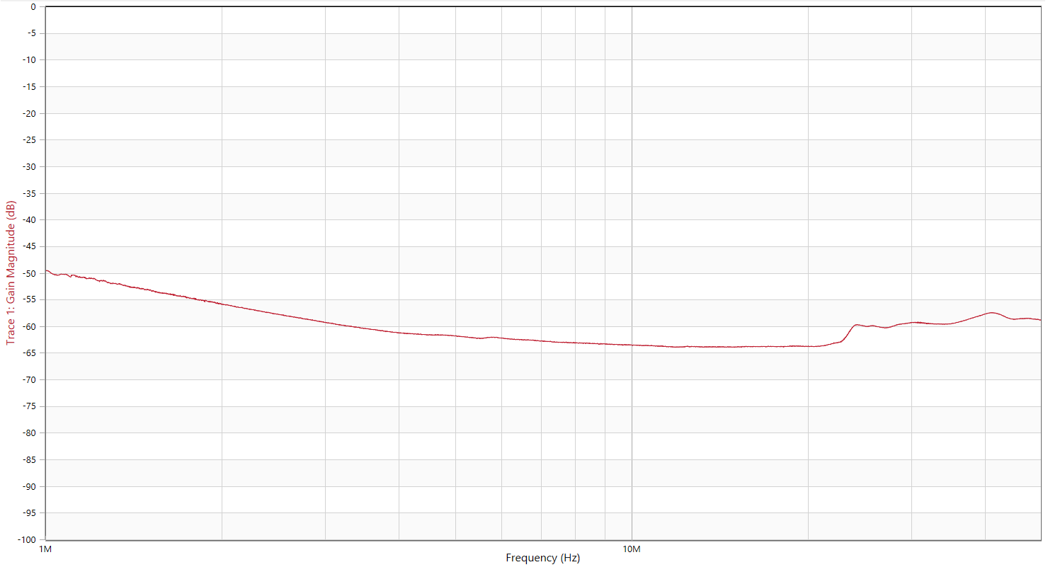
Testing the line injector
![]()
Two main characteristics are relevant for a line injector:
- the highest frequency at which it can inject perturbations
- for a resistive load, how much of the input modulation signals gets seen at the line injector output
The above measurement shows just that, for different resistive load currents.
Here are a few interesting take aways:
- the higher the drawn current, the more high frequencies can get injected
- at >100mA currents the 3dB corner frequency is more than 50MHz
- at (much) less than 10mA not so much input modulation signal will get seen at the output
These last 2 points are nitpicking as they can be "fixed" by simply adding an extra resistor at the line injector output.
Measuring a simple LDO PSRR
Now equipped with my brand new and well characterized line injector, it was time to test stuff!
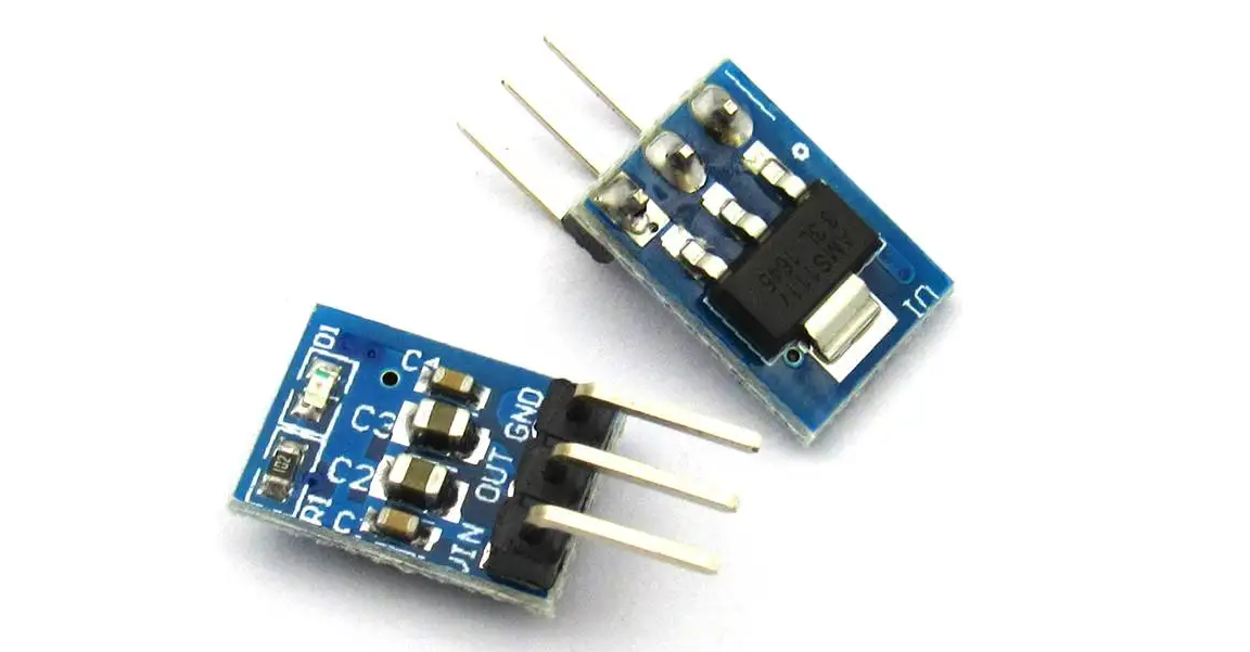
My first victim was a simple AMS1117-3.3 LDO board purchased from Aliexpress.
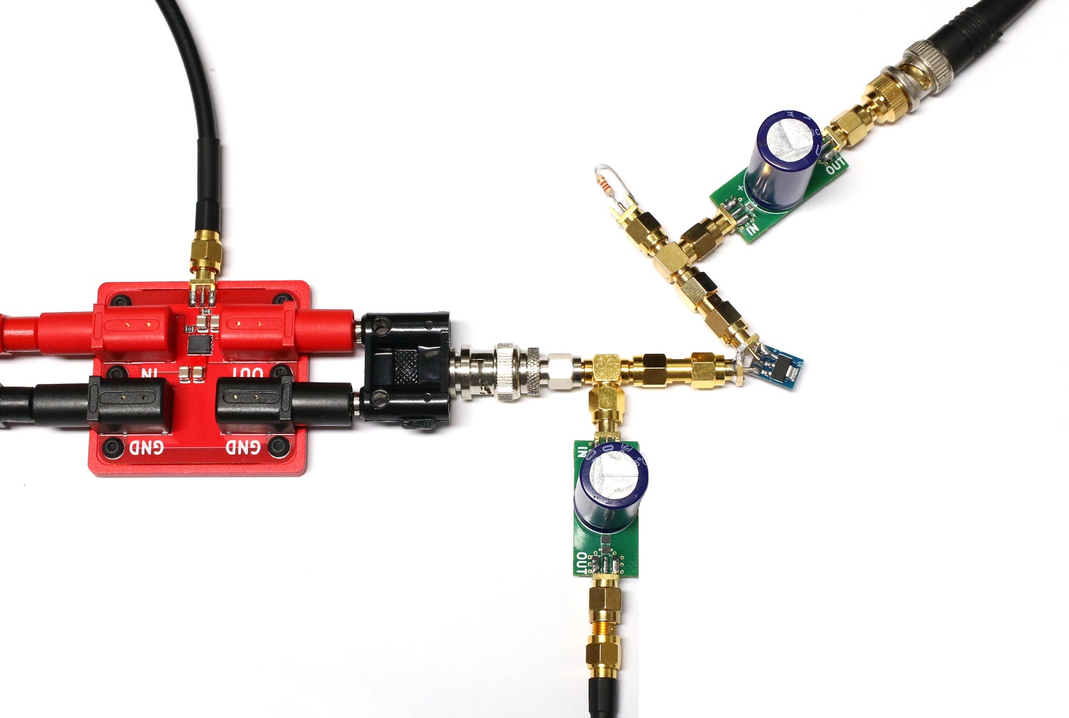
In the above picture you can see the line injector on the left, the LDO board on the right, and 2 of my DC block tapping the power supply AC signal before and after the LDO. Finally, a resistor is put to load the LDO with a few mA.
I then used my low frequency VNA and got the following PSRR measurement:
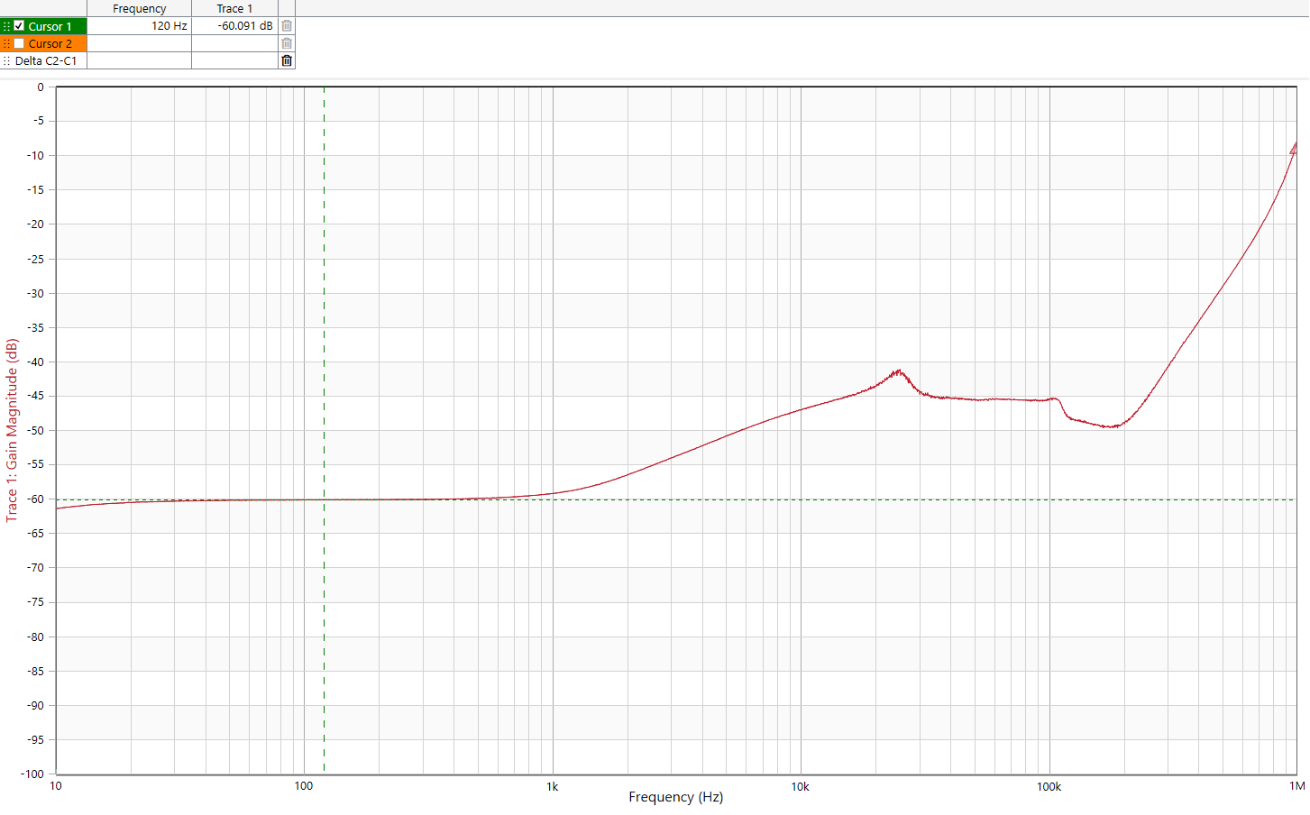
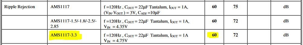
60dB PSRR is in my experience average at low frequencies, but what was more interesting was that it was exactly the value given by the datasheet:
Pretty neat!
Challenges in measuring a 120dB PSRR LDO
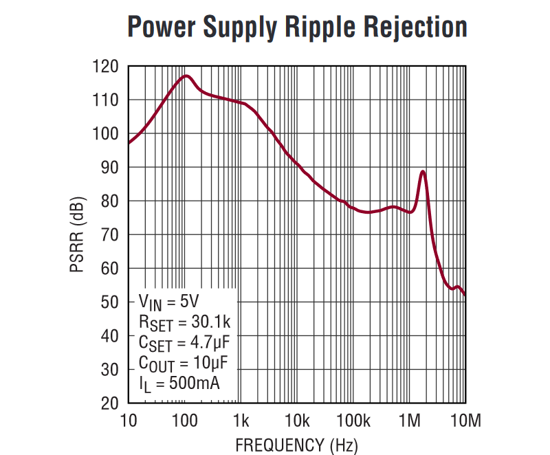
The LT3045 LDO is pretty much the best LDO out there when it comes to PSRR... and it just happened that I had a board laying around with that LDO (and other stuff) with coaxial connectors at the LDO input and output.
I therefore made the same test setup and got the following measurement:
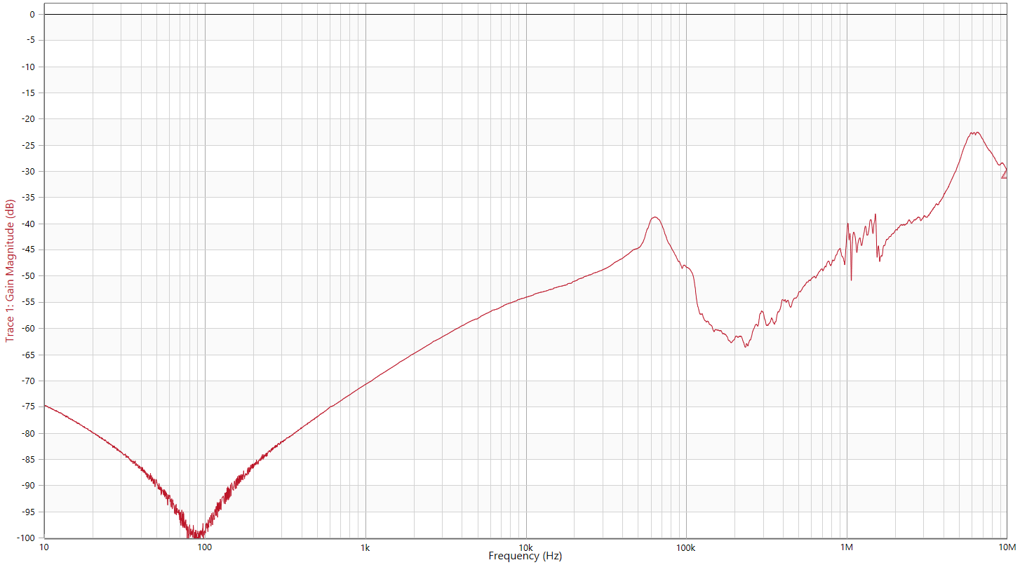
That measurement didn't seem right, as the LT3045 datasheet indicated a higher PSRR. I realized that a high PSRR meant that maybe the LDO output AC signal would be lower than my measurement instrument noise floor.
How to improve that measurement? Use my 34dB low noise amplifier of course!
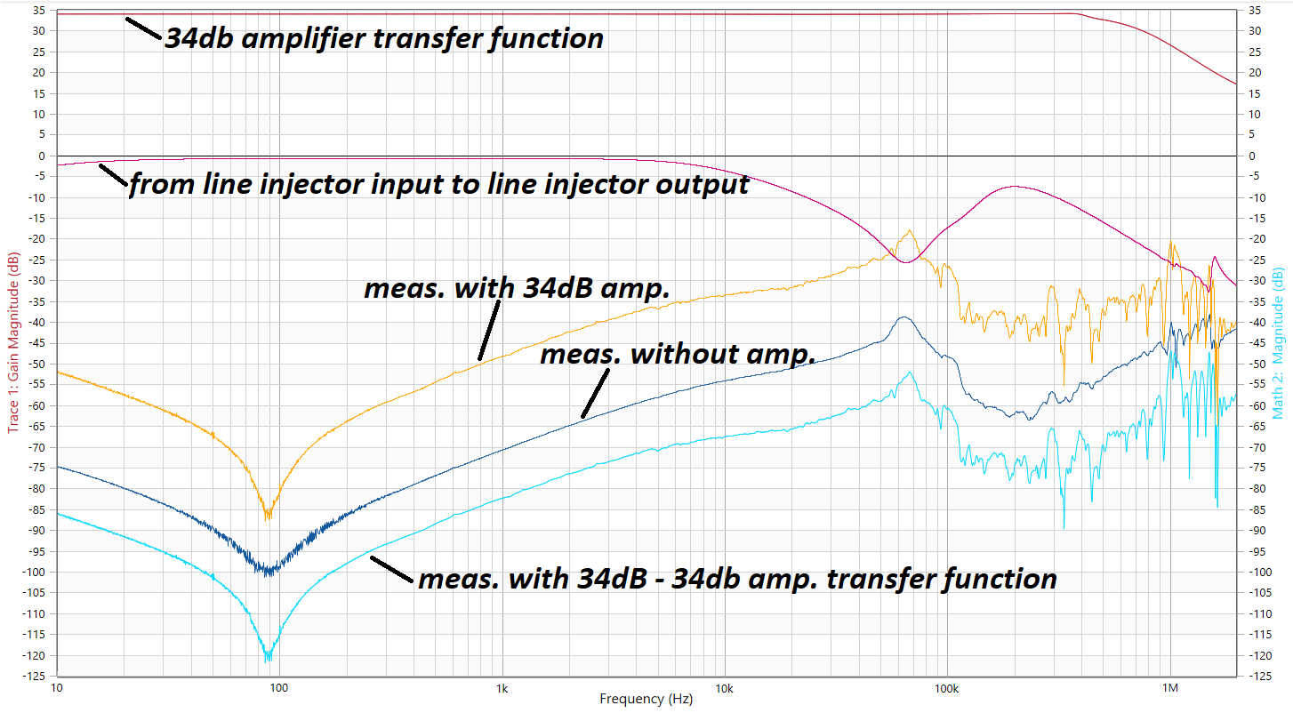
Hopefully you can understand what I did above:
- I made another line injector measurement, with my amplifier
- I measured my amplifier transfer function
- I subtracted my measurement with transfer function to get another PSRR reading
I then "inverted" the result to compare datasheet and measurement side by side:
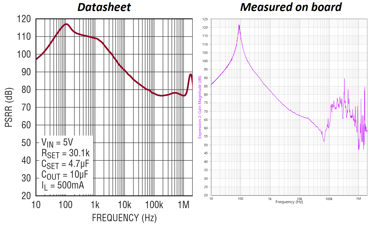
Pretty close! I think the difference between measurement and datasheet can be explained by:
- parasitic coupling between the two VNA inputs (through the PCB or the wiring setup)
- different LDO operating conditions (graph is for 5V operation, I'm using 12V)
- the ICs present on my test board using my LDO output rail
Measuring a simple RC filter
Back to something simpler: a simple RC circuit, or low pass filter.
Do you remember that a capacitor's capacitance changes with its voltage?
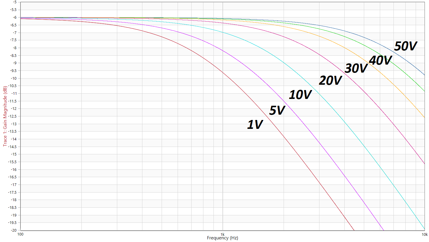
As you can see above, a higher voltage means a smaller capacitance and therefore a higher corner frequency.
Keep this in mind the next time you design a simple low pass filter.
Measuring a Pi filter
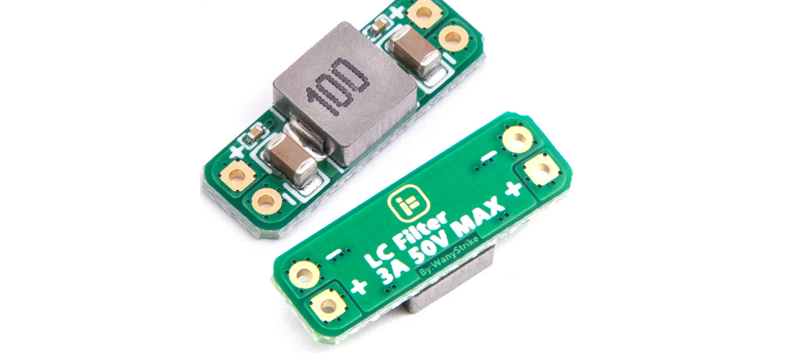
My next victim was an innocent looking Pi filter purchased from Aliexpress.
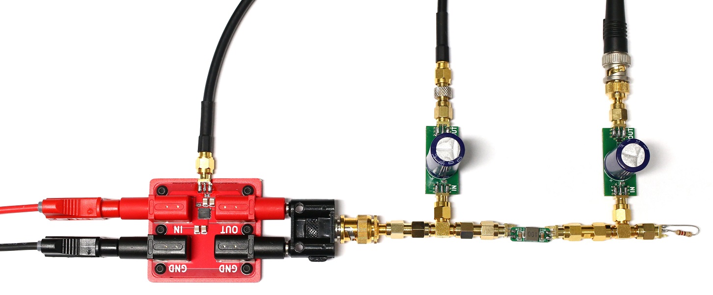
In the above picture you can see the line injector followed by the Pi filter, itself surrounded by two of my DC block which then feed to my low frequency VNA to measure the injected perturbation signal before and after the filter.
Finally, all the way to the right you can see a resistor to load the line injector with 17mA.
I then performed several sweeps for different voltages and got the following amazing traces:
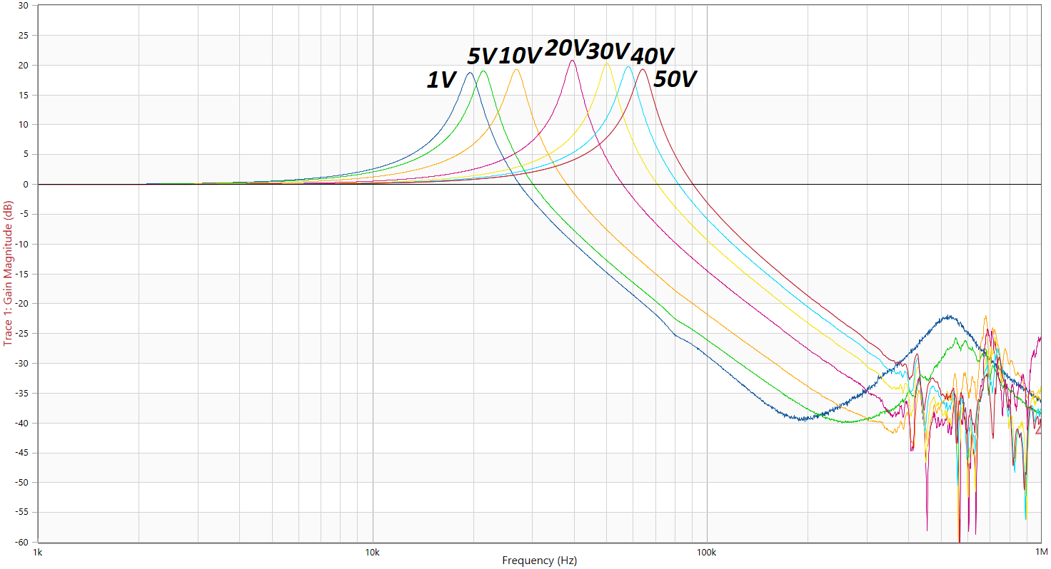
I was quite happy to be able to see the major issue with conventional Pi filters: a major resonance in the kHz frequencies, effectively meaning that at this frequency any noise on your power supply will get amplified!
You'll also notice that the peaks shift depending on the working voltage: this is again due to the fact that a capacitor's capacitance changes with the voltage applied to it.
Measuring an audio amplifier PSRR
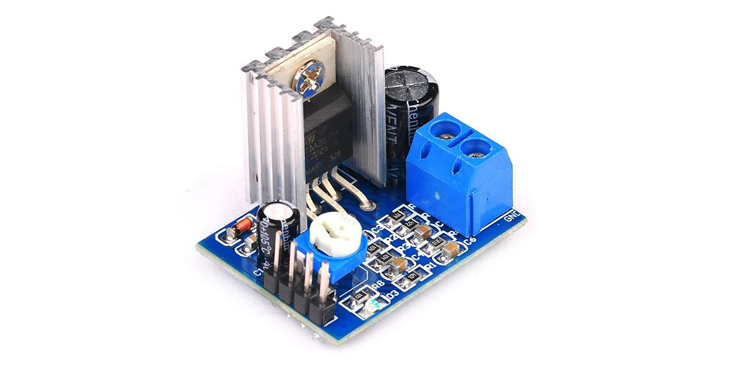
Dabbing my toes into the audio world, I then decided to measure how well a cheap amplifier board could reject noise injected into its power supply rail.
The test setup was fairly simple: the line injector output is connected to the amplifier board supply input while we measure the injected noise and amplifier output when the audio input is shorted to ground.
The TDA2030A amplifier used in the board is actually so old that its datasheet doesn't contain its power supply rejection curve... which is a good thing as the measured PSRR is far from being great!
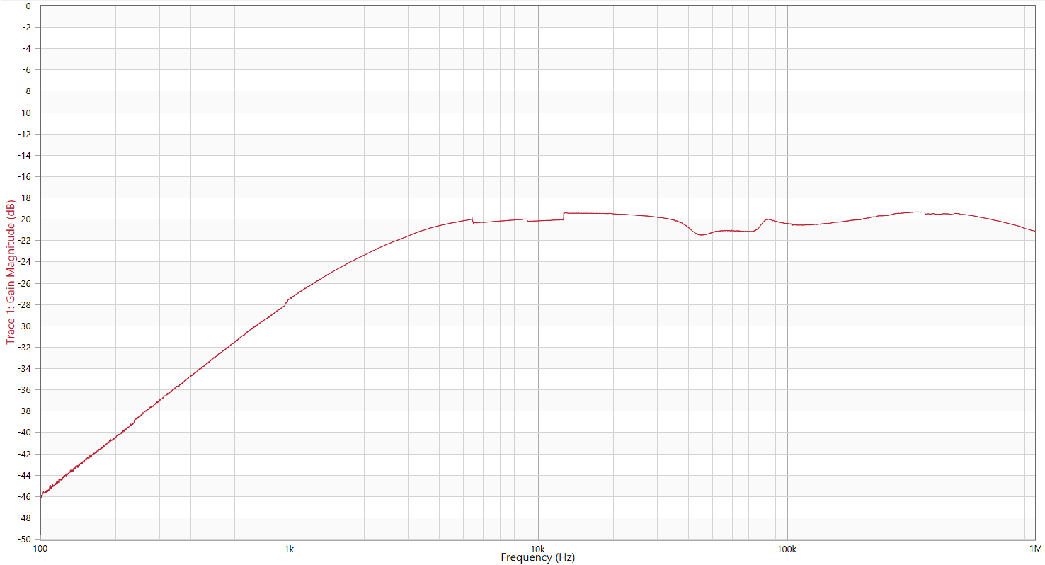
Measuring an RF amplifier PSRR
Essentially the same test as above, but with an RF amplifier instead of an audio amplifier.
Higher frequencies are therefore involved:
As you can see, its PSRR is actually much better than the audio amplifier's!
Conclusion
As you can see, I had lots of fun testing different things with that line injector! I hadn't fully realized it could be so useful.
Do you want one? You can buy one on my stores: US store / EU store.
The source files can be found here.
Cheers!
