CDM324 Doppler Speed Sensor, with FFTs!
By limpkin on Wednesday, August 23 2023, 17:14 - My Projects - Permalink
A very small form factor project, not only measuring an object's speed but also displaying it!
With its UART interface, interfacing with Arduino platforms is dead simple too!
Introduction
If you follow this blog, you may have noticed that this is my third project using doppler sensors, and my second with the CDM324. This tiny sensor is just so neat for its price!
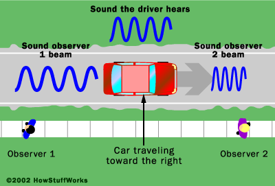
A quick refresher on the Doppler effect: when sending an RF tone at a given frequency towards a moving target, the reflected signal's frequency will be shifted. This is the reason why a fire truck's siren has a higher pitch when the truck is going towards you than when it is still.
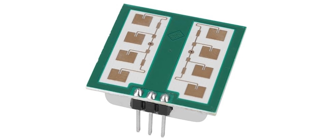
And what's nice with the CDM324 sensor above is that it actually outputs that frequency shift, so you "just" need to measure that frequency to compute the moving object's speed!
The project in action
Before I start getting into the technical details of this project, I figured you may want to see it in action:
Why re-do this project? Why is it better now?
I learned quite a few things about electronics since I first made that amplification circuit for the CDM324 6 years ago.
Here are the main changes implemented in this new version:
- using an FFT to extract the measured speed from the CDM324 output
- using an automatic gain circuit to increase the detection range
- adding an onboard speed display for reading convenience
Computing the Fast Fourrier Transform (FFT) of a given signal esssentially extracts all its frequency contents.
It is therefore more reliable and sensitive than the simple comparator circuit I had previously used, as you effectively look for a big peak in the FFT output and divide its X coordinate by a constant to get your detected object speed.
Sure, it required adding a microcontroller to first digitize that analog signal, but the detected speed can now directly be output through UART.
The previous CDM324 amplification circuit had 84dB of gain which in some cases was not enough. Instead of two fixed gain stages, I'm now using one fixed gain stage and a variable one for up to 92dB of gain (or 40000x voltage gain!). This second gain stage has automatic gain control, automatically varying the overall gain between 72dB and 92dB to hopefully not saturate the overall amplification circuit output.
Finally, as it didn't really make sense for the previous project to require an extra micro-controller to compute the detected speed, this new CDM324 project includes a small display directly displaying the detected object speed to the user.
Digging into the Analog Circuit
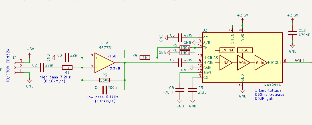
Starting from left to right, you'll first see the fixed gain stage of 130 (42.3dB) with a 7.2Hz high pass filter (C2 & R1) and a 6.1kHz low pass filter (R3 & C4). This allows progressively filtering out speeds not between 0.16km/h and 138km/h.
This particular op-amp was selected for its low input noise and high power-supply rejection ratio.
As it's only powered by 3v3, its positive input is set to a fixed voltage generated by the next amplification IC. This effectively allows us to bias (or center) the op-amp output to a voltage between its two power supply rails (0V and 3.3V).
The second amplification stage... is a microphone amplifier!
Thinking about it, it made perfect sense using an amplifier made for the exact same frequencies I was interested in, especially when it comes with automatic gain circuitry. It'll therefore automatically amplify less if your speeding object is close to the sensor, and amplify more if the the object is far away. Cherry on top of the cake, its output voltage is already centered around 1.23V so there's no need to re-bias it before feeding it to the microcontroller's Analog to Digital Converter (ADC).
What About the Digital Circuitry?
The digital circuitry is simply composed of an STM32F301 microcontroller and an I2C-controlled LCD segment driver.
The STM32F301 was selected for its small package, relatively low price and Cortex M4 core which can easily compute FFTs (more on that later).
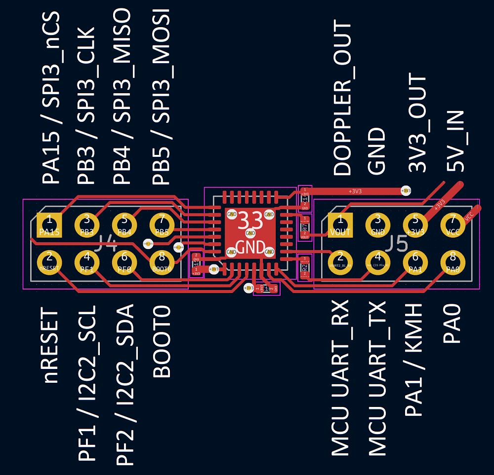
As there was still some board space available during the layout stage, I also broke out a full I2C and SPI bus to 2 expansion connectors... and that's on top of the existing UART bus for MCU flashing and the spare IOs/reset/boot signals!
I therefore fully hope to develop some expansion boards that would plug to that module.
A TN display was selected for its size and readability: it's of the same type that the ones used in multimeters.
Reading the measured speed in a bright environment therefore shouldn't be an issue! It's however quite tricky to drive as it requires some interesting waveforms, and while I had thought of letting the MCU directly drive it for a moment, the number of resistors required to do so made me go for the embedded controller you see in the above schematics. Interestingly, you'll find online some people who did manage to pull it off!
As a side note, I had originally gone for a 7 segments display, but the current transient when changing digits was so high that the introduced perturbation on the CDM324 5V rail would lead to glitches in its output:

Things Worth Mentioning
I figured I'd make a dedicated paragraph to mention the things I really like about this little board.
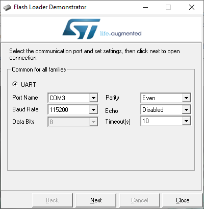
No programmers are required to update the MCU: the STM32F301 comes with an embedded UART bootloader! By simply connecting a USB-UART adapter to the dedicated connector, tying the BOOT0 pin to 3V3 and then briefly bringing the RESET pin to ground, the STM32F301 will enter bootloader mode.
The overall circuit is very simple and expandable: there are only a handful of components and the two expansion connectors with I2C, SPI, UART and IOs will hopefully enable projects from electronics enthusiasts!
The PCB
The folks at PCBWay.com were kind enough to sponsor this project!
As usual, the quality was great, shipping was fast with DHL, PCB assembly was without any issue so the PCB worked right away... these days I always go with them.
I'm pretty sure this is the one of the most compact PCB I've ever laid out. It's only 32 by 32.5mm and is made to be put behind the CDM324. A general rule when amplifying small signals is to have as short traces as possible!
Measuring the Transfer Function
To make sure the amplification chain could sense the speeds I was interested in, I needed to measure the circuit amplification across frequency.
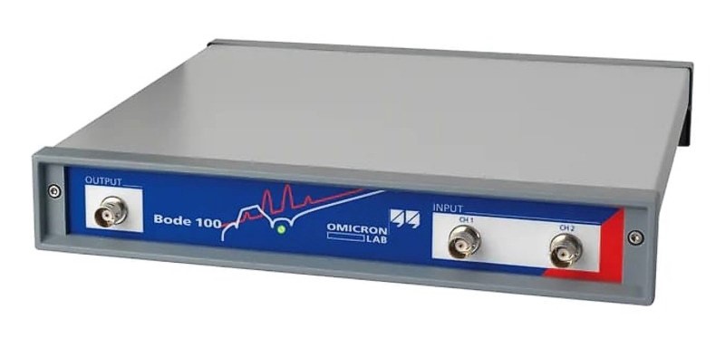
To do so, I used my Bode100 but could definitely had manually done it using a signal generator and an oscilloscope (it just would have taken longer). Given the extremely high amplification present in the analog circuitry, I used many attenuators (for a total of 80dB!) at the Bode100 output to present a -100dBm signal at the amplification chain input (that's 6.3uV peak peak).
Using a large averaging factor and a 10Hz measurement bandwidth, the following graph was gotten 10 hours later:
Let's ignore for the moment the overall gain and focus on the -3dB corner frequencies, even though it's a bit ironic to do so when dealing with such a high circuit gain. While the measured low pass corner frequency was bang on (6.1kHz), the same couldn't be said of the high pass filter corner frequency. The reason was then found inside the microphone amplifier datasheet:
Even though this is actually fine as a 100Hz frequency corresponds to a 2.3km/h speed, I still took that opportunity to update my first amplification stage to the following:
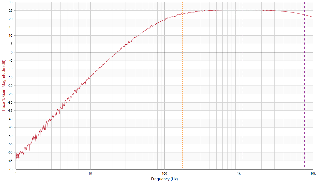
I then ran another frequency sweep (this time with 70dB of external attenuation) and got this:
... and if we zoom in between the -3dB corner frequencies:
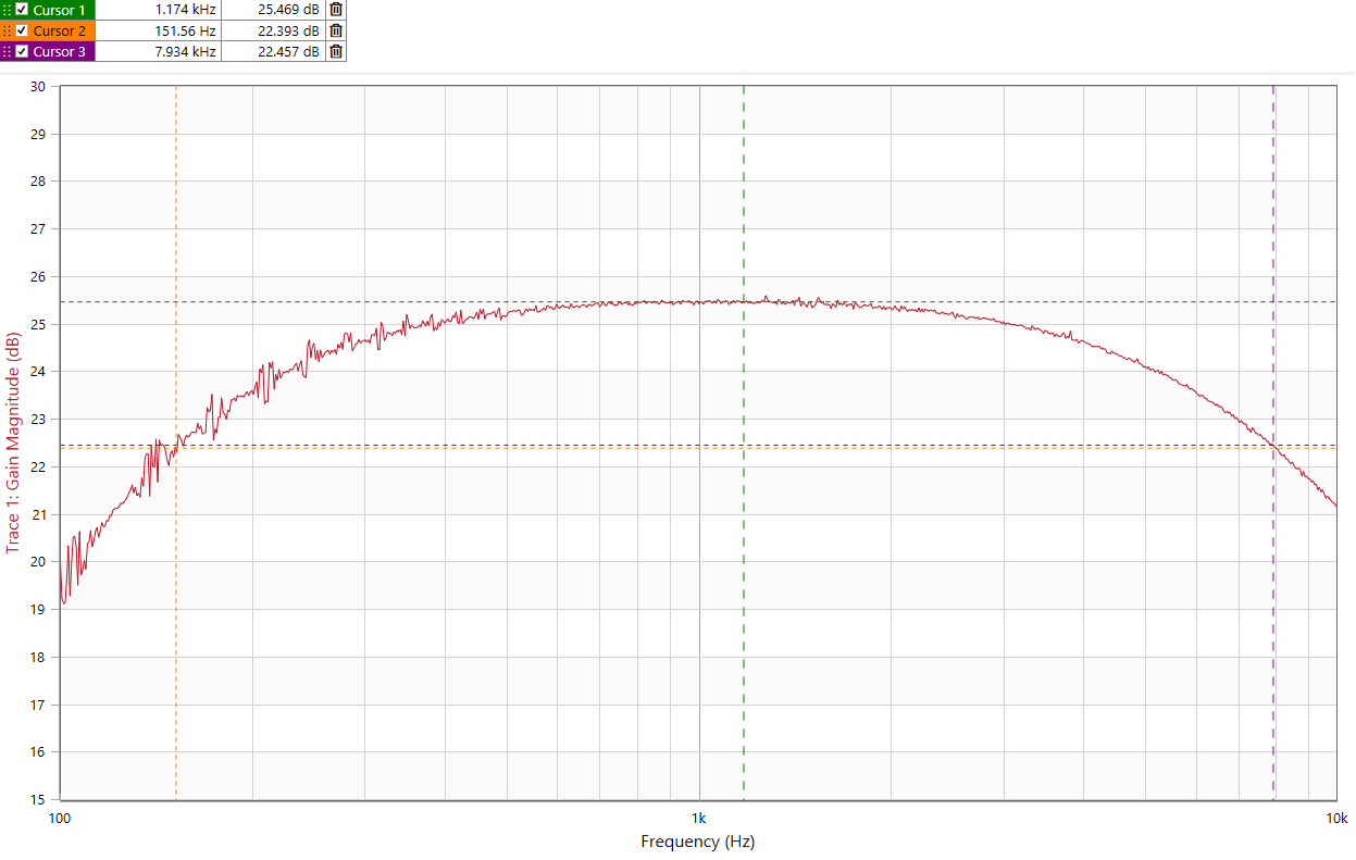
Taking into account the 70dB of external attenuation, the overall amplification gain ended up being 95.4dB, with 3dB corner frequencies of 150Hz (3.4km/h) and ~7.9kHz (180km/h).
Finally, here's a very interesting way to test the microphone amplifier automatic gain control feature: in the below measurement, I not only perform a frequency sweep but also a power sweep:
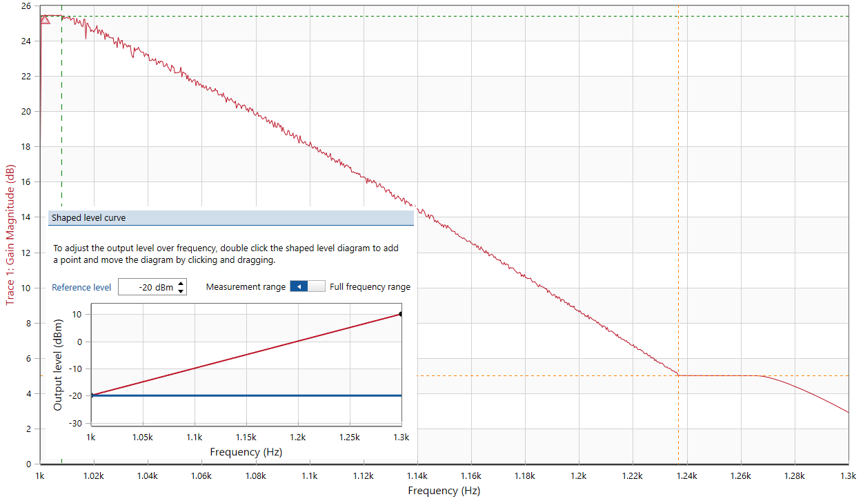
Given that I'm linearly sweeping between -90dBm and -60dBm between 1kHz and 1.3kHz, we can conclude that the AGC starts kicking at an input power of -89.9dBm and seems to stop intervening at -66.3dBm. This 23.6dB range is however a bit high as the datasheet mentions 20dB.
Checking for Oscillations

An extremely common issue when having an amplification chain with such a massive gain is oscillations: without any signal present at your device input, when probing your output you'd typically see a rogue sine wave.
This happens when some of your output signal gets coupled into the device input (imagine putting a live microphone in front of speakers).
But how does it get coupled? you may then ask.
In my experience either through electromagnetic coupling (output PCB trace close to the input trace) or through power supplies (a current draw proportional to the output signal introduces a voltage drop on the first amplifier supply which then gets coupled into the input signal).
While one could typically use an oscilloscope to measure the amplification chain output signal to check for small oscillations, one would be limited by said oscilloscope input noise level. One way to get around that could be to use my low noise amplifier board but I instead went with my SA44B spectrum analyzer and got the following spectrum:
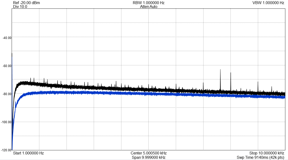
The black trace is the output spectrum with a CDM324 connected and the blue trace is the output spectrum with a 50 ohms resistor connected to the amplification chain input.
The blue curve being below the black curve means that my amplification chain noise floor is below the CDM324 output "noise"! This means the complete device is "limited" by the CDM324.... which is what I wanted to see.
Also worth mentioning is the relative lack of pronounced spikes that could be caused the AC grid frequency, TN display scanning or USB lines: remember that the above measurement was taken with a very sensitive spectrum analyzer while the cdm324 was standing still. What really matters is that the spectrum computed by the STM32 is flat when nothing is moving around.
If we "walk back" the amplification chain we can try to compute our amplification chain input noise rating: -80dB (noise level at 1kHz) + 21dB (500 / 50r resistor divider at the specan input) - 95.4dB (circuit amplification) = -154.4dB/sq(Hz) = 4.26nV RMS/sq(Hz).
Comparing that value to the theoretical one can be done using the following formula from that document (from page 6):
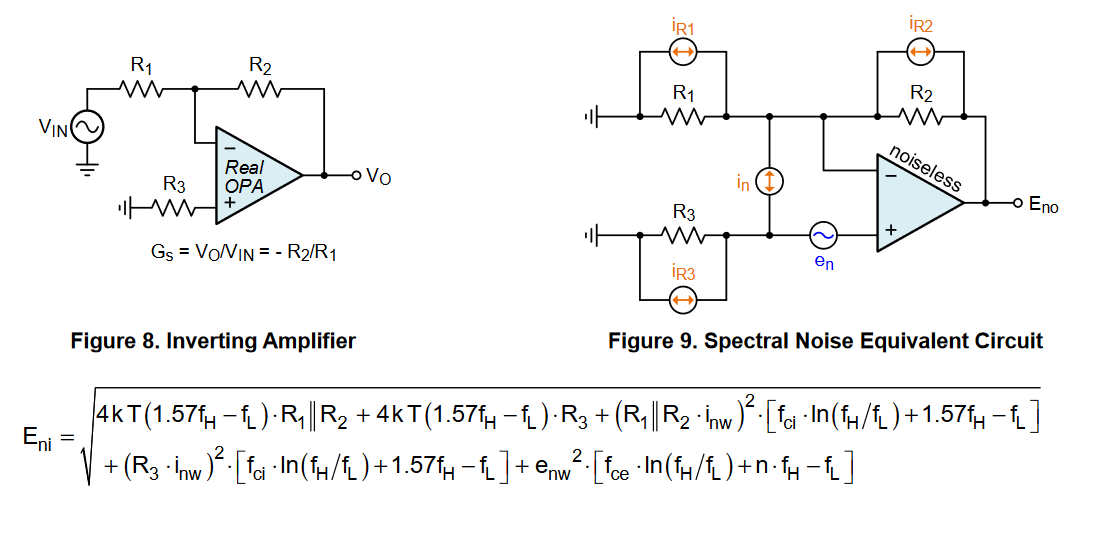
Rather than doing these math however, one may notice that this 4.26nV/sq(Hz) measurement is already below the 4k7 input resistor johnson noise of 8.7nV/sq(Hz)... and I'm not even mentioning the LMP7731 input voltage noise (2.7nV/sq(Hz)) and LMP7731 input current noise (1.1pA/sq(Hz)) going to the 4k7//620k.
I wish I had an explanation for that difference... but I repeated that measurement several times, even used a signal generator and a table top multimeter to double check the circuit amplification (I actually measured more than 95.4dB)... but still couldn't find an explanation on that better than expected result. If you're reading this and have an idea, send me a message and I'll send you a device for free!
Mechanical Assembly
Similarly to my previous CDM324 project, I've designed and 3D printed a small support to hold everything together.
The overal assembly only measures 36x36.5x17.5mm. Tiny!
MCU Performance & ADC Sampling Rate
You may know that FFT computation is quite resource intensive.
In a "release' build configuration, by toggling a MCU pin I measured that 2.4ms was needed to:
- convert 1024 ADC samples to floats
- compute a 1024 points FFT
- compute the magnitude of the FFT output vector elements
This effectively translates to a maximum of 417 FFTs per second, which is more than enough for our purposes!
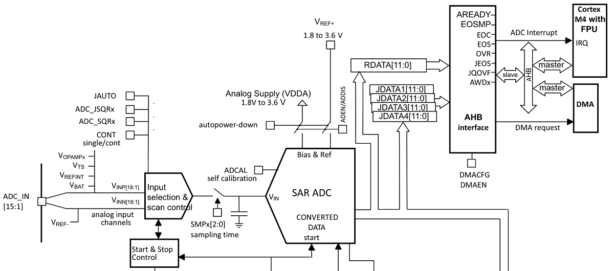
I therefore selected an ADC sampling rate of 35.7ks/s, meaning that for a 1024 samples buffer I should theoretically be able to measure frequencies between 34.9Hz and 17.8KHz (or a minimum of 0.8km/h). That also meant an FFT frequency bin width of 0.8km/h (0.5mph).
By using double buffering (one buffer filling with data while another is getting processed), 34.9 FFTs per second can be computed. If we want to stream raw ADC values and FFT data through UART, a minimum bit rate of 34.9*(1024*uint16 + 512*float32)*10/8 = 1428kb/s is required. But because of baud rate incompatibilities between the MCU & possible USB to UART adapters, that actually means a 2Mbit/s minimum baud rate.
However, it turned out that many USB to UART adapters couldn't handle a continuous 2Mbit/s stream.
In the scripts located at the end of this page, you'll therefore notice that I actually use 1Mbit/s, and am only sending the "interesting" part of the FFT data.
One last thing to mention: I did find that the required impedance between signal source and ADC input needed to be small, as otherwise what seems to be a current bias would be introduced during the sampling phase.... odd.
On the topic of Hardware Abstraction Layers
When it comes to Hardware Abstraction Layers (HALs) everyone has his/her own opinions.
I personally tried several of them (for different platforms and IDEs) and until now have been quite against using them as it'd always take me as much time learning the HAL as I'd spend reading the datasheet.
With the STM32 environment, things are quite different: you actually get a nice graphical user interface (STM32CubeMX, also embedded in the STM32CubeIDE) that allows you to fully configure your microcontroller and its internal peripherals (think Clocks, SPIs, UARTs, Timers, Interrupts, DMA transfers...). Once you save your .ioc file, the IDE will automatically generate the HAL initialization code and interrupt routines in 3 files (main.c, stm32f3xx_hal_msp.c, stm32f3xx_it.c) and you'll be more or less good to go.
Why more or less? Well in the case of configured timers, it'll still be up to you to call the actual HAL start routines depending on your use case (HAL_TIM_Base_Start, HAL_TIM_Base_Start_IT, HAL_TIM_Base_Start_DMA...). Luckily, given the STM32 platform is used all over the globe, the time between realizing something doesn't work and the time you find a solution online will be less than a few minutes. Getting something up and running is therefore extremely quick.
However... there are times where the code generation tool messes with your complete software solution. It happened to me once that when changing an SPI baud rate in STM32CubeMX and saving the changes my platform wouldn't boot anymore. After comparing my main.c with a previous version (don't forget to use code versioning!) I discovered that the generated code initializing the external crystal driver had simply disappeared!
Moreover, while relying on this code generation tool is great when wanting to rapidly tweak a few settings... it actually prevents you from compartimentalizing your code in different files. Even though I managed to do so, identifying all the functions and global variables that are required for a given feature rapidly gets annoying (think interrupt routines for peripherals and DMA transfers, end of transfer HAL callbacks, HAL descriptor objects...).
You also obviously get a performance hit as the HAL performs a few checks before letting you do what you'd like to. For a simple 24bits SPI TX transfer I actually measured a performance penalty factor of 9 between using the HAL and directly writing the registers myself. STM however does also provide a Low Layer API (LL), with "better optimization but less portability, requiring deep knowledge of the MCU and peripheral specifications."... but at this point you may as well go bare-metal :).
Writing a Debug GUI
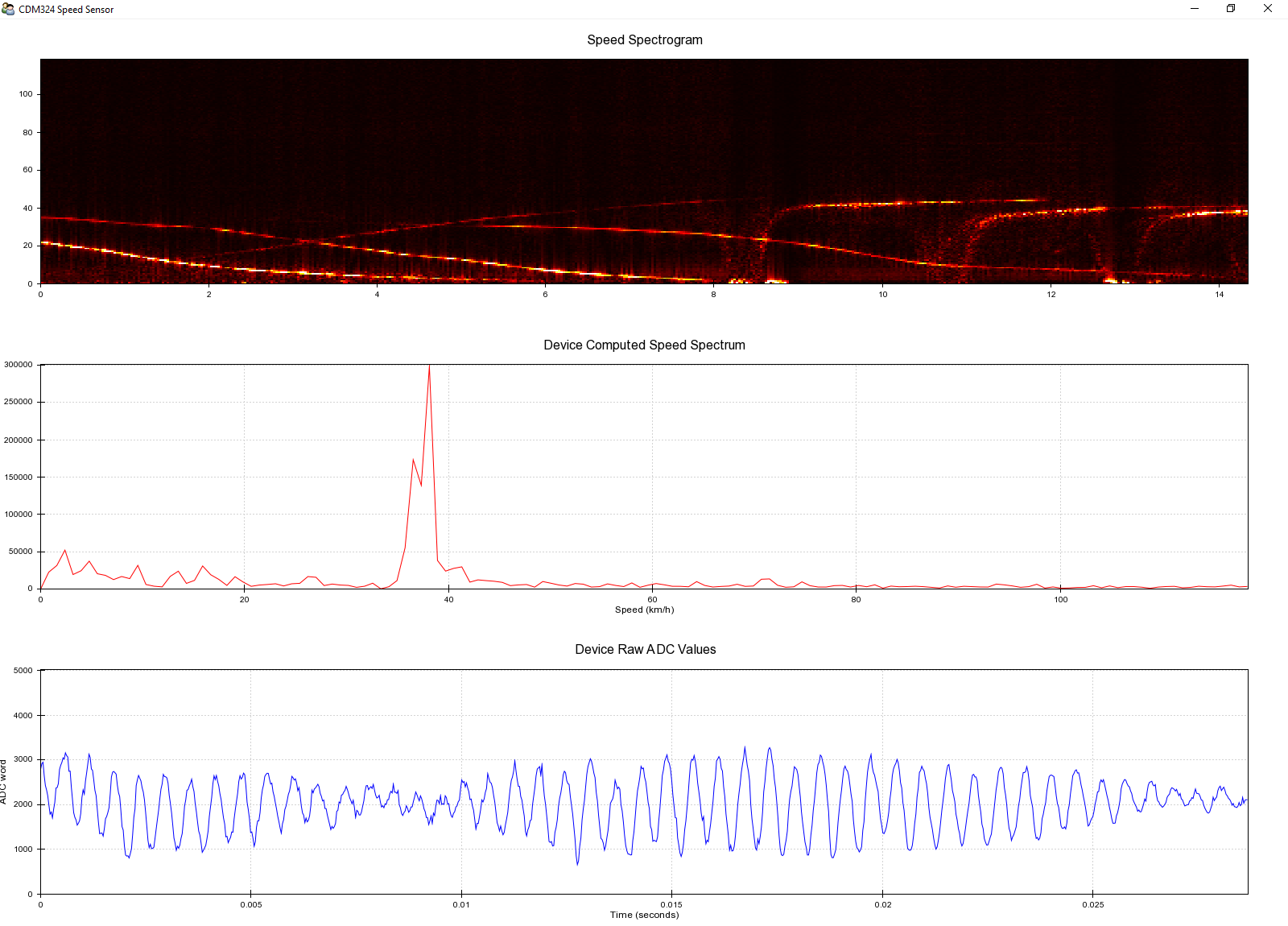
Can you guess the cars passing me by and the ones stopping next to me?
As previously mentioned, the onboard MCU can use its UART peripheral to output data to the outside world.
For debugging purposes (and nice demo effect), I therefore wrote a python GUI that leverages the Enthought Chaco framework (itself based on qt4) to display live data on your computer screen.
Depending on your computer configuration, it can (surprisingly) handle a 1600*1200 pixels window at a refresh rate of 34 frames per second to show raw ADC samples, computed FFT data and detected peaks over time.
So sensitive that it can debug your computer
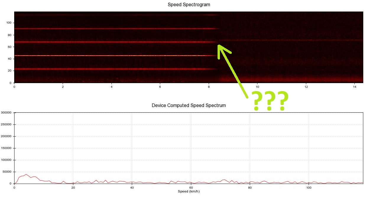
Remember when I mentioned that I switched from a 7 segment display to a TN display because of voltage transients?
In the picture above you can see the output spectrogram when no movement is happening in front of the sensor. At that moment, the AGC is not kicking in and the gain is at its maximum (94dB). That means the board amplifies.... everything, and that includes potential noise present on your USB power supply!
So what happened at the end of that green arrow? I'm pretty sure it has something to do with either my trackpad or power saving features as this transition only happens when not touching my laptop for 30 seconds. I'm assuming the noise is picked up through the USB +5V power line, but it could also also be picked up through RF.... fun, right?
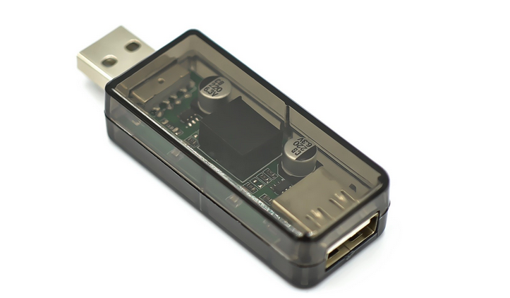
A way to improve things is to use a USB isolator as the one pictured above though!
Making a Companion Board
As it seems I was particularly motivated by this project, I then took some additional time to make a breakout board.
It offers the following features:
- a USB to UART converter, connected to the RESET & BOOT0 lines
- a jack connector so you can listen to the doppler noise
- a switch to toggle between MPH and KM/H display
- a uSD card connector to log speeds
That 1.6mm PCB with its two 8pins connectors means that it's firmly attached to the CDM324 module!
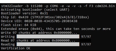
Something great that is now enabled is one click firmware updates using the RTS & DTS lines of the USB-UART converter and the stm32loader project... how awesome is that? All you need to type is:
Tying it all together: making a Control GUI
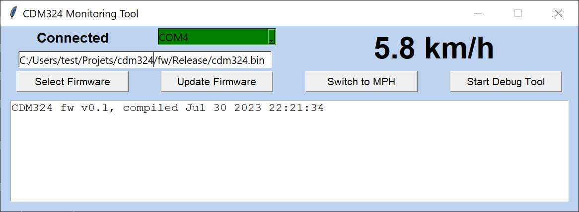
Rather than having a collection of scripts, I decided to make a single python tool that:
- automatically fetches and displays the detected object's speed
- launches the speed debug tool I previously mentioned
- allows you to flash the device
This is just the beginning, pull requests are strongly welcome!
Project source files
As with all my other projects, you'll find all source files made for this project here!
Want to buy the complete assembled device? Have a look at my US shop or EU shop!
Want to interface that sensor to an Arduino? Have a look at the getting started instructions.
Thanks a lot for reading!

Comments
This looks amazing. Are the parts available for purchase and shipping to the US?
@SROBINSON: of course: https://www.tindie.com/products/ste...
The article does not give the range being detected, as far as I can see.
How accurate is the data from different distances?
Hi, I was wondering if this could be used to measure the speed of a softball/baseball? My daughter is a softball pitcher and it would be interesting the measure the speed of her pitches from the position of the catcher. There are commercial products but the are expensive https://www.pocketradar.com/product... Also could this be adapted to drive a large display like tjishttps://www.aliexpress.com/item/325... to be seen from further away?
@Bj: placed close enough, the sensor could absolutely measure that speed... and you could use one of the spare bus on the connectors to interface with a (custom) display of some sort yes.
Hello! Excellent job and explaination too!
I would like to use it to measure the speed of tennis ball.
Would it be capable? If yes, how close enough have to place it?
Will be any benefit at high speed balls if i increase low pass filter from 7.9kHz to 9-10 khz but at the same time make higher the high pass from 72 Hz to 200-250 hz ? (i don't care about low speed balls).
Hi Mathieu,
Many thanks for designing and producing this CDM324 project. I purchased a complete kit from your online Tindie store (CDM324 sensor display module, expander board and USB isolator. The kit arrived within 8 days from China and worked first time on assembly and powering up.
I was very pleased to see that the ST32F301 had already been programmed with the CDM324 software - many thanks, this has saved me hours, since I'm not a Windows 10 user and normally use Linux and Chromebooks.
I haven't had a chance to 'borrow' a Windows machine to try out the GUI debug software, but have used a Python script to manually read the mph and km data over the serial port by issuing 'm' and 'k' command characters respectively, to retrieve the latest speed values .
I did notice that by issuing 'a' there is a continuous stream of data output that varies if I wave my hand in front of the radar sensor. I could not find the command to switch back to 'normal' mode. Is this mode normally controlled by the GUI debug software.
I couldn't find any information about SD card operation, is this already programmed into the STF301? I was just a bit worried about turning the power on and off to the back pack if an SD card was present.
Thank you once again for all the time and effort you have put into this project, it is much appreciated and has helped me greatly progress with the building of a vehicle speed monitor for the local community.
Kind Regards,
Peter
@vagyver: thanks a lot! that's a tough one... would say fairly close (<30cm) as the ball is not metallic. I think you could only modify the low pass filter without touching the high pass one :)
@Peterf: thanks for the kind words, they mean a lot! It seems you have a good overview of the ecosystem :). The counterpart of 'a' is 's'.
About SD card: nothing is programmed at the moment, but the low level routines are there: https://github.com/limpkin/cdm324_f...
You may need to format the card with a 512 block size. Send me a quick email at (mydomainname)@(mydomainname).fr for faster communication :)
Hi,
I've just received my board and it works amazingly! I'm hoping to tie this into another arduino board to run as a speed sign.
Is there a way to get it to only show the speed of things coming towards the sensor, rather than away from it?
thanks
@Will:
Thanks a lot for the kind words!
At the moment I haven't coded this functionality yet, but in theory it shouldn't be that complex as we would need to store the "FFT energy" and check if it increases or decreases over time to know if the object is moving toward / away from the device :)
Awesome work with this. I am starting to look into doppler radar for a particular project and stumbled across your older board for the HB100. Imagine my surprise finding this project!
I am nowhere near your level of understanding of the programing for this project let alone the circuitry, but have found a need in my neck of the woods for a reasonably priced speed detector.
I am wondering two things:
Could this be calibrated to display feet per second(seems this would be the easy one),
And could the circuit be optimized to detect between say, 200fps and 350fps(219kph-329kph)?
I've read through the amplification circuit section but don't have the background knowledge to take a stab at answering this one.
Thank you!
@Shawn: thanks a lot! changing to feet per second is an easy one indeed. modifying the circuit for 329kph seems to be just on the border of what is possible (due to the max BW of the MAX9814). I however don't know how well the sensor itself would work :)
Hello again!
I just received it and i can't wait to use it outdoorly!
But i have 2 questions:
a) I used the gnd and the 'TX" pins and drive a usb-to-uart ft232rl adapter set at 115200 so that i can have the output value but i got nothing.
Do i have to do something else, since i am not using your usb board?
b) Since i couldn't find schematics, does the circuit have a voltage regulator? If yes, we could supply it with more than 5V. and then please, how high voltage? If not, then we have to supply with exact 5V (i am afraid since cdm324 is 5V, you might haven't used any).
I am asking because now i am using a lM317 and i want to get rid of it.
Mamy bravo your the build quality and the very very careful design!
@vagyer:
1) it should work right away, you may try to power cycle the sensor to see an hello message output by the sensor
2) schematics can be found at https://github.com/limpkin/cdm324_f... . The circuit does have a voltage regulator, you need 5V exactly.
thanks for the kind words!
Unfortunately, what i only get is a welcome mesaage.
This:
CDM324 fw v0.1, compiled Aug 15 2023 23:41:17
And this happens when i set the baud rate at 10001000 (and not at 115200 as expected).
And then nothing at the serial port. At the same time, i see values on the lcd.
The question:
Could it be in bootloader mode?
Have i to make a pin high or low to get values?
Have you even test it without youe serial board like i try to do?
@vagyver: 115200 is NOT expected, I invite you to have a quick glance at getting started instruction in the readme : https://github.com/limpkin/cdm324_f...
Well, i have to adnit that all information was there!
I found everything and the board is working! As your documentation says!
BUT, what i am investgating now is that i get multi values at the serial compared to the lcd.
If i send the 'm' and the lcd displays 0.8, i get 8 and the serial. If the lcd 2.3, the uart says 23.
When i send 'k' i get even more larger values at the serial.
I am still investigating why....
@vagyer: simply divide by 10 the value returned by the serial link :). 'm' is for mph, 'k' is for kph
Does the current code support setting of the angle of the sensor to the direction of the object being measured (eg if you are measuring vehicle speed but the sensor has to be angled to the road so that the sensor can be placed off the road)?
Does it also support showing the maximum speed for each 'object' between each idle phase, rather than the live speed? To explain more: In the example video of the trains, the display shows the live, varying speed of each train, so it would be difficult for someone watching the display to work out what the maximum speed for each train was. In the scenario I'm thinking of (measuring the maximum speeds of cars on a road) it would be great if the display would just show the maximum speed so far between each idle phase, rather than it varying continually.
Thanks!
@bill: for the angle attack, here are the lines you'd need to modify with an additional multiplication: https://github.com/limpkin/cdm324_f...
Modifying the code to "freeze" the maximum speed is fairly straight forward to! I might actually have some time to do it :)
Thanks for the pointer to the code!
Well, i have to say i got very positively suprized by its accuracy up to 80 km/h which i tested it with my car!
I got usually up to 2 km/h differnce with the car's odometer! Amazing! (and if cars display 1-2 kmh more than real, then no difference!)
Amazing!
My notes are that for those who didn't buy the uart board (like me), i had to find that i have to ground the km/miles pin so that i can see km instead of miles and divide via 10 the usart reading. Quite some lost time!
But i did make a nice code keeping the maximum speed for 6 seconds and i got really fun using it! So happy !
So, please consider at your next update maybe add/modify any of these.
Finally, can you recommend any modifications (maybe at the opamp gain or the filter's freqs) so that i measure my tennis serve speed?
Have you any experience with small objects?
Thank in advance!
@vagyer: thanks for the kind words! I've updated the readme to mention the tying to ground trick :).
Unless you serve at more than 200km/h I don't think you need to make any modification.... however if you see that the speed is not picked up, maybe we could modify the high pass filter to filter speeds below 50km/h. to be honest I'm not sure if how sensitive the radar will be
Hey, I also purchased the kit from your Tindie store and am eager to get my project to monitor the average speeds of the road outside our house off the ground. I was just wondering if you have any recommendations about waterproofing and/or enclosures. From my understanding plastic and glass should be transparent at these frequencies so I was thinking of just using a normal plastic project box and sealing it all up with silicone before installing it outside. I'll probably use PoE to get power and data to/from the box but will just seal that exit point as well.
@Dave: plastic or glass boxes will indeed work! Your plan sounds like a good one.
Hi
I recently bought 3 devices for testing with my MCU MKR1310, just a quick question is it possible to have the sensor inside a box to weatherproof the sensor or would it not work well inside a box?
@Johan: it'll work well inside a box :)
Could this device be used with a Raspberry Pi, instead of an Arduino?
Is it possible to just steer the device without the extender board true a ESP32 ? which gives a solid 3.3v from the board.
And it would be possible then to steer a 7 segment led strip board?
Gruss aus Zuri
@Craig: yes of course :)
@mike: definitely possible as you'd just need the UART connection. I'm not sure what you mean by your second question?
Trying to load the Gui nevertheless recieve all kinds of errors can you let me know to what Python version it works ?
Python 3.12 and 3.11 gives errors on treats and the 2.7 does not allow pip install
Reffering to my other Question,
The intention would be to add a esp32 to grab the speed which i hope is visable in the serial
Which i would like to display the speed on a 7 segment ledstrip display
https://youtu.be/r_yobwaBWr0?t=766
Bassically building my own maximum speed display
@mike: could you let me know the errors? 3.12 and 3.11 should work
your project should work indeed, simply grab the speed through uart :)
Hi, the new version looks very nice!
I am interested in measuring the speed of water flowing inside an irrigation canal.
The sensor will be positioned a little bit above the surface, at an angle.
Is it possible to measure speeds as low as 2.5km/h?
@Homer: I honestly don't see why not :)
Would it be possible to modify the output to give distance travelled, assuming the sensor is pointed towards the ground at 45 degrees?
In the application I have in mind, some output filtering would be needed to take into account an uneven surface (ploughed field).
Speeds travelled will be between 1 - 6 kph.
@SeanG: I don't think integrating the speed would provide reliable distance measurement for long distances...
Hi, you have done some great work here and it’s much appreciated!
I am trying to use the backpack board to record to the SD. You mentioned some additional software above, and to format the card with a 512 block size.
My questions are:
1) Should I format the card as NTFS, FAT, or ExFat file system, and do you mean 512bytes or kilobytes?
2) Do I need to use your reflashing PC software to install onto the board the SDcard software you linked in the comment above? I’m nervous about overwriting the software already on the board so any specific instructions would be welcome .
3) What do the two buttons on the board do?
Thank you!
Hi Dave!
1) FAT, 512 bytes
2) just to make it clear, at the moment the logging functionality is not implemented so you'll need to compile the firmware yourself. you'll need to use either my tool or the others i mentioned to flash the new firmware. no worries about bricking, you'll always be able to reflash the board
3) they drive the MCU BOOT0 and RST pins :)
Very nice projet, can we mesure the speed of a ball ( like football ) thanks to your project ?
hi Valentin!
Yes of course :)
Was anybody successfull to be able to read the KMH value from the device ?
In the meantime i have order another unit which seemed atleast able to start and show on the gui nevertheless after a while it again stopped functioning.
I need to be able to grab the value to display it on other devices. but the Python stuff is so terrible instable that you can even normally update the CDM with a lower baudrate.
Is there anybody willing to share a bit of code / picture how they started using this device as i am currently lost.
BTW I am under the impression you have to remove the expander board to direct read the values ?
example code used.
// WiFi credentials
const char* ssid = "xxxx";
const char* password = "cxxxxx";
ESP8266WebServer server(80);
SoftwareSerial cdm324Serial(D2, D3); // RX, TX for software serial. Adjust pins as needed
unsigned long previousMillis = 0; // Stores the last time the "k" command was sent
const long interval = 5000; // Interval at which to send the command (milliseconds)
void issueCDM324Reset() {
 while(cdm324Serial.available() > 0) {
   cdm324Serial.read(); // Flush any existing data
 }
}
String getSpeed() {
 while (cdm324Serial.available() == 0); // Wait for data
 String speedStr = cdm324Serial.readStringUntil('\n');
 float speed = speedStr.toFloat();
 return String(speed / 10); // Assuming the speed is sent in decimeters per second
}
void setup() {
 WiFi.begin(ssid, password);
 while (WiFi.status() != WL_CONNECTED) {
   delay(500);
   Serial.print(".");
 }
Serial.print("Connected, IP address: "); Serial.println(WiFi.localIP());server.on("/", HTTP_GET, []() { String speed = getSpeed(); String html = "<!DOCTYPE html><html><head><meta name=\"viewport\" content=\"width=device-width, initial-scale=1.0\"><title>Speed Sensor Data</title></head><body><h1>Speed Value: " + speed + " km/h</h1></body></html>"; server.send(200, "text/html", html); });}
void loop() {
 unsigned long currentMillis = millis();
 if (currentMillis - previousMillis >= interval) {
   previousMillis = currentMillis; // Save the last time the "k" command was sent
   cdm324Serial.print('k'); // Send the "k" command to the sensor
 }
}
@Mike: what error do you get when using the GUI? I never had issues on my side...
You shouldn't have 2 devices connected at the same time to the CDM324, as it will create short circuits!
What board are you using? what's your wiring configuration?
Your code seems good, but I don't know how the esp board handles concurrency...
Changed the approach.
Just trying to grab the details trough a RASPBERRY
import serial
import time
ser = serial.Serial('/dev/ttyUSB0', 9600, timeout=1) # Open serial port at 9600 baud
try:
   while True:
       line = ser.readline().decode('utf-8').rstrip()  # Read a line and decode it to a string
       if line:  # If the line is not empty
           print("Received:", line)
       time.sleep(0.1)  # Wait a bit before reading again
except KeyboardInterrupt:
print("Program terminated by user")finally:
Nevertheless when running the code the display on the device freezes until you stop the script
I have now tried 3 separate instances to use this device
Win10 (Gui Code unstable)
Win11 (Even more unstable)
Raspbery pi (freezes the device)
Even bought a new 1 nevertheless if remains extreemly unstable and has no working configs. using the device might be ok nevertheless not if you like to integrate it to something.
@Mike:
If you're using the expansion board you may need to add the following lines, as the RTS/CTS line control the reset/boot0 lines:
ser.set_buffer_size(rx_size = 1000000, tx_size = 1000000)
ser.serial.rts = False
I am modifing your low and high pass filter value so that i can measure tennis speed ball.
High pass will be 1540 hz so 35 km (so i will get rid of some noise). The low pass 9240 hz so 210 km (so i will welcome some more noise here).
But i have to say, during my calculations that your 4.7K resistor has 8.7nV/sqHz noise and the LMP7731 has 2.7nV/sqHz noise.
But i think it is not very efficient to have dominant noise from resistance. Opamp's noise should be dominant noise contributor.
Of course by lowering 4.7K resistor maybe mismatch with CDM324's high impendance, so will have less real gain. That might means that havt to increase 620K.
Have you any data/thoughts on these?
If you want, I will let you know my results on my investigation/changings.
I ordered the board + extension in Switzerland and paid
paid €36 and an additional €16.36 for taxes/shipping.
That's a lot, because you now have to wait another 2 weeks for shipping from CHINA.
You can only see that the goods come from CHINA if you accidentally scroll to the bottom of the order page.
It is unexplainable to me why there is no warehousing in Switzerland or better in France.
I had expected that, as with all Arduino applications, you would get a simple output on the serial port.
This is obviously not possible.
You probably have to do as described here https://github.com/limpkin/cdm324_f...
visualstudio build-tools and python, with about 5GB.
I just managed to do that with outside help.
Btw "pip" does not work at all...
And if it does, "pip install pyqt5 chaco stm32loader pyserial" ends with an error for me:
   " note: This error originates from a subprocess, and is likely not a problem with pip.
     ERROR: Failed building wheel for enable
     Failed to build chaco enable
     ERROR: Could not build wheels for chaco, enable, which is required to install pyproject.toml-based projects"
I can't get any further. This is really unedifying and a waste of time.
So, please provide a ready-made program (exe) with which you can log the data securely and flash a firmware easily.
Then even non-programmers can do something with your hardware.
I also don't know how to connect the part a few meters to the street without any problems.
With 1000000 baud, that's not exactly out of the question. Yes, there is also a 57600-bin, but I doubt that I will be able to flash it.
I've also often had problems with USB extensions.
Now I also have an alternative running; only with an Arduino Nano.
Also with FFT and that works wonderfully, but I need a simple horn antenna for amplification.
Here I only transmit the 5V and the amplified low-frequency signal, so only 3 wires are needed in a shielded cable.
This means that the transmission is undemanding and easy to accomplish. The Arduino is in the living room and writes to a serial monitor.
Btw, together with the fantastic ArduSpreadsheet tool https://circuitjournal.com/arduino-... I can then log wonderfully.
And it is also easy to customize the output in the Arduino script.
Maybe you can also change your serial interface so that this ArduSpreadsheet tool runs directly with your hardware.
That would be superb.
It would also be great to have an ESP software with which you can get the data into your house via WLAN.
That probably wouldn't be too difficult, but unfortunately I can't do it.
In any case, you could significantly expand the user/customer base for your radar hardware.
Unfortunately, I can't do much with your radar hardware at the moment:
I can only stand by the road myself and then read the LCD.
And even this is only possible in bright light, as the LCD has no illumination.
@pirx: I'm very sorry about your experience... Of these 16.36EUR, 8.36 is for VAT (19%) and 8 is for shipping and handling (preparing the package + actual shipping fee). I'm not making any money from this 16.36. I'm afraid that if I had to setup a fulfillment center in France or Switzerland then I'd have to actually charge more.
You can actually get a simple output from the serial port: simply type 'm' (for mph) or 'k' (for kmh) in your favorite terminal program, as described in github: https://github.com/limpkin/cdm324_f...
Regarding your issue, did you manage to install the c++ build tools without any issue?
Do I correctly understand you want to setup a several meters long serial link? I'm afraid that due to physics you won't be able to make it work, but active USB extension cables will work in that case.
Thanks for the feature suggestions! It's definitely something we can implement.
Looking forward to your reply.
Thanks for your quick answer.
"did you manage to install the c++ build tools without any issue?"
YES
"you want to setup a several meters long serial link?"
Yes, it seems I have to. Or do you have a better solution?
"but active USB extension cables will work in that case."
Also with 1 MBAUD?
"simple output from the serial port: simply type 'm' (for mph) or 'k' (for kmh)"
Yes this works manually.
Do you have/know a terminal program which can do this automatically?
There better should be a mode in your Software for automatically sending the results.
I just had some strange results:
The LCD was showing constant 251.0 !
Then after some movement, it was coming back to normal behavior.
Do you know this Phenomenon?
@pirx:
- could you do a "pip install wheel" and try again the install process ?
- using a 5meters long active USB extension cable connected to my expansion board (or a usb to uart adapter with short cables) will work indeed
- at the moment I didn't code a mode where the speed is periodically output, but it's something that could easily be implemented! do you have experience in coding?
- regarding the 251.0 reading: there can be a number of reason, the most likely being electro magnetic perturbation in your environment
"pip install wheel" works but does not help. Same error at the end.
Unfortunately my programming skills are very poor.
No knowledge of python, simple AutoHotkey scripts and small changes in the Arduino code are fine.
@pirx: can you try "pip install enable" and try again?
"pip install enable" is not working:
Failed to build enable
ERROR: Could not build wheels for enable, which is required to install pyproject.toml-based projects
@pirx: I got the same error message on a computer where the build tools weren't installed. could you redo these steps?
https://github.com/limpkin/cdm324_f...---windows
Hi,
I am very satisfied by the quality of the kit I received which included the speed sensor, the expansion board and the USB isolator. Thank you very much.
As many, I was looking for an instrument to get the car's speed in front of my house. I would like to save the data and do some statistics.
I read the blog thread and thought it is possible. I am not a developper. I am familiar with Python due to some experience with Raspberry Pi (I tried a Speed Detector with a Rpi, its camera and OpenCV). But I used more Arduinos, ESP 32 and ESP 8266. I am often travelling in "Terra Incognita" and it takes time. I read more carefully the blog, the comments and the readme on Github.
At first the only communication way with the sensor is serial TX/RX because I2C is not implemented despite the connector available on the expansion board. For my first test I used an ESP32 because it has two full serial ports. But it failed.
In order to use a slower baud rate I turned my interest to the bootloader and dug into Visual Station Code. I encountered a new trap with the install of chaco. Hopefully Limpkin was faster than me to solve the problem.
1. The Bootloader
Using the bootloader I was able to change the baud rate to 57600.
============================================================================
PS C:\Users\henri> stm32loader -b 115200 -p COM3 -e -w -v -s -f F3 "C:\Users\henri\...\cdm324_57600.bin"
Activating bootloader (select UART)
Bootloader activation timeout -- retrying
Bootloader version: 0x31
Chip id: 0x439 (STM32F301xx/302x4(6/8)/318xx)
Device UID: 002F-0031-5243570A-20313238
Flash size: 64 KiB
Extended erase (0x44), this can take ten seconds or more
Write 138 chunks at address 0x8000000...
Writing ████████████████████████████████ 138/138
Read 138 chunks at address 0x8000000...
Reading ████████████████████████████████ 138/138
Verification OK
PS C:\Users\henri>
============================================================================
2. Checking USB Serial communication
I connected the expansion board to my PC. I checked Windows Device Manager, found USB-SERIAL CH340 (COM6) and changed the settings to 57600 bauds. Using the Serial Monitor of the Arduino IDE, on COM6 at 57600 bauds, when resetting by the expansion board button, I got the message : "CDM324 fw v0.1, compiled Oct 3 2023 16:11:55". But sending "k" gave sometimes an answer but not often.
Nota : If I use a cable USB-C <-> USB-C to the USB-C connector of my computer, the speed sensor screen shows "291.9". And also some of my USB-A <-> USB-C cables seem not working properly (no sound on connection) despite the fact I use them to other purposes.
3. Using the GUI
At first I replaced the baud rate of 1000000 by 57600 in the script:
- stream_visualizer.py (lines 253-254)
- cdm324_device.py (lines 29-30).
I connected the expansion board to my computer by USB, it's on COM8 set at 57600 bauds. Then :
python "C:\Users\henri\...\cdm324_fft-main\scripts\_start.py"
and I got the CDM324 Monitoring Tool.
Unfortunately it did not connect. The port field changed alternatively from COM4 to COM8 with the background color in white, but nothing occurs. When I disconnect the USB cable, the backcolor of the COM field becomes red with the warning "No COM ports detected!"
Nota : pushing the Debug button, I got some information (https://github.com/limpkin/cdm324_f...)
4. FDTI232
My connections are :
Speed Sensor FDTI232
When I disconnect J6 nRESET, I get the message "CDM324 fw v0.1, compiled Oct 3 2023 16:11:55"
And when I send a "k" I get an answer (value x 10) on each try.
My next step will be to come back to the ESP32 to check the communication with the sensor. Then, to save the speed of an object, it's necessary to solve one problem : the sensor answers only when "k" is sent like the cop's handheld radar when he pushes on the trigger. It is possible to add a presence detector (with an acute angle of detection) to do that, or by software to send "k" continuously in order to receive a flow of values and filter them to get useful data.
Best regards.
Henri
@hdeb: thanks a lot for the kind words!
So I just re-tried on my end flashing the 57600 firmware, modifying line 29 of _start.py to change '1000000' with '57600' and managed to get the GUI (not debug tool) running.
Please note that the debug tool will NOT work with a 57600 firmware as the baud rate will simply limit what's possible to broadcast.
I'm however confused, as you originally mentioned the expansion board but then at step 4 you mention the FTDI232?
I'd personally regularly send 'k' to get speed data and do processing on the esp32 side :)
Hi limkin,
as you know, unfortunately the python issue is not solved.
But it seems you have ESP-solution/code:
"I'd personally regularly send 'k' to get speed data and do processing on the esp32 side :)"
Does this solution also connect the PC by WLAN?
And can you share the code?
@pirx: I'm still trying to understand what is wrong on your computer setup when I can't replicate anything on any other computer indeed.
I'm not sure to follow you when you say that I have an ESP solution. I'm only suggesting to have the platform connected to the cdm324 (in this case the esp32) regularly send 'k' to get speed data.
The code I'm suggesting is the one on the github page: https://github.com/limpkin/cdm324_f...
@limkin
Sorry, I misunderstood you.
Yes, I had already seen the interface solution with the Arduino.
Unfortunately, I would still have the cable problem to the PC.
It would be great if you could provide an ESP program with a WLAN interface to the PC.
Then I wouldn't necessarily need to solve the Python problem.
Another question:
What can you say about the accuracy of your measuring unit?
@pirx: to make sure I follow you correctly: you'd like me to write some code running on an ESP development platform to broadcast speed data wirelessly to a computer?
The accuracy on the measurement unit will mainly be dedicated by how straight you'd be pointing the sensor at incoming objects. If directly straight, I'd expect less than 3% measurement error.
@limkin
"follow you correctly:..." YES, this would be great!
The accuracy sounds good! If there is an angle in the radar-view, I could correct with cosinus of the angle:
v_object = v_measured / cos(a)
@pirx: what esp dev platform exactly? with esp-idf? micropython? what about the receiving side? python ok?
@limkin
I normally use ESPhome, that would be perfect.
I would use an esp8266.
Output to a "text sensor" would be OK.
There must be a timestamp with milli-seconds.
So something like 2024-04-28 13:00:22.991;36.3;84327702
Where the 2nd number is the milliseconds of the processor, if possible.
This means that I only need the YAML code.
Please no Python, that doesn't work for me.
One more question:
How can I flash the other firmware with 57600 baud (cdm324_57600.bin ) but without Python?
@pirx: I'm very sorry, I don't know YAML. To flash without the GUI, simply follow this: https://github.com/limpkin/cdm324_f...
I bought 2 of your CDM324 devices and I am trying to use the SPI interface. I am doing a write b'm' and reading from SPI afterward. SPI just sending me b'\x00\x00\x00\x00\x00\x00\x00\x00\x00\x00'
Does the SPI interface work at all?
I configured the baudrate to 100000 and another time 1000000, same result.
@John: at the moment, only UART communication is available, nothing is implemented at the SPI level. I'm extremely sorry if I wrote anything that would indicate so, but adding support should be fairly straight forward :)
I got the UART working without the expansion board. Everything looks good. baudrate = 1000000, sending "m" and getting the value from whatever is on the screen. But there is a problem. Without the expansion board, I am not getting the speed of a vehicle from both the screen and uart.
With the expansion board, the speed of a passing vehicle is showing correctly.
I now want to connect the usb port of the expansion board as a usb serial. I tried it by connecting usb-c to usb-A to my PC and opening up putty I was able to communicate baudrate 1000000 and send "m" and getting the right value as a reply whatever is showing in the screen of the sensor.
Originally, I got the raspberry pi zero 2w setup and configure this to use the serial port. /dev/serial0 works to communicate to the sensor directly with no problem using baudrate 1000000. The only issue was, can't get the speed working. (without the expansion board as stated above)
So now, I need to connect a raspberry pi zero 2w using the expansion board usb, but I don't seem to be able to get this working. I google the pi zero 2w and was told to setup the config.txt to add dtoverlay=dw2. Everything looks good, /dev/ttyUSB0 appears and I can write to it, but can't read anything back using baudrate 1000000
Can you suggest a solution? I need to powerup using the expansion board. Can I insert 3 pin (Tx,Rx,Gnd) to the original sensor port and get a uart reading?
There is a setup in pi zero 2w to get the usb serial to work that you know of?
Finally found the culprit on my Rasp Pi Zero 2W. My Pi is also setup as an Access Point, which consume power. (I will have to test this out tomorrow if without the Pi providing WiFi, if this is enough for the Pi to provide power to the radar.)
When I power the Speed microwave radar sensor independent from the Pi and the Pi uart is the only connection (and ground) to the radar sensor, the sensor is giving the right reading.
Ignore my previous comment about the board expander.
@John: oh thanks for sharing with us the solution to that issue :)
great bit kit, would it be possible to do a idiots guide to setting it up with link to PC / Arduino as i am a total Noob to python and programming . as i would like to monitor the radar remotely as to monitor traffic out side my house
TIA
@matt: sure! can you let me know what the guide on https://github.com/limpkin/cdm324_f... is missing?
Anyone having trouble getting it to work with ESP8266 should do two things.
Flash the firmware to ensure a baud rate of 57600, using https://github.com/limpkin/cdm324_f... (see flashing instructions at https://github.com/limpkin/cdm324_f...) and then use the sample at https://github.com/limpkin/cdm324_f... while using Software Serial:
Replace all mentions of "Serial1" in the sample code with "mySerial" (because Serial1 is already used for ESP8266, so you cannot use it).
Any reason why a "quiet" CDM384 would report roughly 58 mph, constantly? I tried different boards, and all show the same number. When I hold it and move toward a wall it shows the correct speed. It does not seem to respond to a car that's driving towards the sensor.
In the absence of a signal, the device reports 57-58 mph, always. I sample every 500ms. This occurs at both baud rates, both firmware, different CDM324 devices. However, note that it only happens when the UART is connected! Any explanation?
@Thomer: thanks for the tips! Regarding idle 58mph reading that could be due to your power supply or environment :). We could change the firmware in such a way to be less sensitive if you prefer :)
Yes, please! I'd love to experiment with a less sensitive firmware.
Also, this happens with different power supplies. And only when UART is connected. If I disconnect the UART the built-in display shows the correct numbers...
Is there a way to use the i2c interface? Maybe that might solve the problem since otherwise the problem only occurs with UART. Can you document the interface?
@Thomer: great! let's talk by email. I'm afraid the current firmware doesn't implement anything through i2c
Hello, I am trying to investigate why althought it counts correctly the tennis ball speed some tines, but sometines it does not.
So, i thought the timing issue might be the problem. I am explaining:
You said (in your very nice detailed analysis) that fft processing takes 2.4 ms.
What about adc sampling?
If you use 35,7 ks/s, which is 28 us. So x 1024 samples = 28,6 ms, then a whole cycle takes 28.6+2.4= 31 ms (and i haven't include display time).
If ball travels with 150 km/h (which is 41.6 m/s speed) then the ball speed 1,28 meters. Which means only 3 full cycles sampling in the about 4 meters space i have (which is the distance between the cdm324 sensor and to the server's racket).
And what about display time? Do you have clue, how much it is? Because during 2.4 ms and display time, no measuremnt is made. So, loss of info (for tennis ball. For car or train, no problem).
So, do you think that might the problem?
if that is correct, do you think, it might help, reducing the samples from 1024 to 512 in in order to sample the ball's speed more times?
An other idea is to alter the code and once it detects frequency more that 2 khz (which is 2k/44= 45 km/h speed) it will captures several group of samples (let's say for 2 secs) and after that it does the fft calculate. But that might cause memory limitations.
Wrong thinking?
Thank you in advance and sorry for the long story here.
@vagyer: ADC sampling is done continuously and results are transferred through DMA so a cycle technically lasts for 28.6ms (the FFT is done at the same time). You'd indeed have around 3 full cycles.
I think your problem may be due to the average being done: https://github.com/limpkin/cdm324_f... so you may want to remove that code :)
Hello again!
Based on your answer above, i think i must investigate removing averaging. (if it works perfectly, i will let you know all the changes i did).
Well, since i am not familiar with STM32 family, i have a small question:
@vagyver: sounds like a plan! the bootloader is part of the MCU itself so you don't have to worry about bricking anything! Simply compile the solution and upload the bin using the commands described in the github readme :). I'd definitely recommend using my expansion board so you don't need to press any button as the program will generate the right signals to start the bootloader
Many thanks for your work - just tried first time and it works nicely!
Even on Linux (Ubuntu 22.04), here is what I had to do, just in case somebody cares:
1) Had to run as root to access /dev/ttyUSB0 (possibly avoidable be joining group "dialout", not tested yet). Also, the debug view loads a lib which requires root (the pure non-debug GUI works after temporarily "sudo chmod o+rw /dev/ttyUSB0")
2) Therefore: sudo pip3 install -r requirements.txt
3) Possibly in addition the following is needed:
4) Modify _start.py and stream_visualizer.py
Modify cdm324_device.py and stream_visualizer.py
5) Plug the device in
6) sudo python _start.py
7) :-)
@tge: thanks a lot for your feedback! I'm sure this will be useful to others :)
Hello again!
I have news!! Good news!
I managed to change the firmware using the STMCubeProgramming Software, which is waaaaaay easier!
So, i recommend to investigate it (if you are willing to make changes in the firmware, like me).
And a question:
Limpin Owner, have you done any firmware update?
@vagyer: oh, I never actually tried the STMCubeProgramming Software. I'm not sure what you mean by your question, but I've indeed used many different tools to perform firmware updates.
Great v2 of the previous 6 year old project! Thank you for sharing it with us. I am not familair with the STM32 as far as programming and I would like to make some of my own tweaks to the hardware and the software. I think I am ok with the adapting the hardware configuration (faster op amp speed/low-high-pass) as I want to measure nerfgun/airgun pellets up to 1100fps. Yes, the CDM324 is being used in a commercial pocket radar chronograph for up to 1200fps. What I need help with (and I failed in the past) is the FFT. I would like to use the Arduino IDE and the nRF52 Nordic chips (but no the Nordic SDK). Do you have the FFT code in C++ or in Arduino language? If not, how can I "human read" the STM32 FFT code? Thank you very much!
@Tommy: thanks for the kind words! For the FFT code, it's as simple as this function call: https://github.com/limpkin/cdm324_f...
Hello limpkin,
I am about to purchase your komplete hardwareset of your CDM 324 project. I am not expirienced of programming the STM32, I am using the Arduino (328P). So do I get the sourcecode when i buy your package? The reason is: I want to apply some changes. E.g. A Triggerpoint to trigger a external Flashlight :-) for a defined speed.
Regards
Rudi
@rudi: thanks for your interest! the source code can actually be found here: https://github.com/limpkin/cdm324_f... you'll need to use stm32cube :)
Hi limpkin,
Thx for your quick response. I have ordered the complete package in Lausanne. As a retired electronic / radio / Tv specialist I hope
I will handle the software issues with your project :-)
Have a good time
Rudi
@rudi: thanks a lot! if you wanna meet in person, do not hesitate to send me an email!
Hi
I have the sensor and companion board.
Has anyone managed to get this working on a Raspberry Pi, I have exactly the same issue as described by @Mike in comment 43, and have tried adding the lines as suggested in comment 44 to no avail?
If someone has a working Raspberry Pi script can they please share?
@Martin: which script are you running? please note that the baud rate is 1000000 and not 9600 as in comment 43 (unless you flash the alternative firmware)