Repairing a Pair of Audioengine A5 Speakers
By limpkin on Tuesday, September 5 2023, 20:37 - Others - Permalink
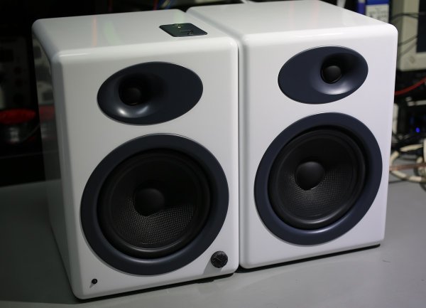
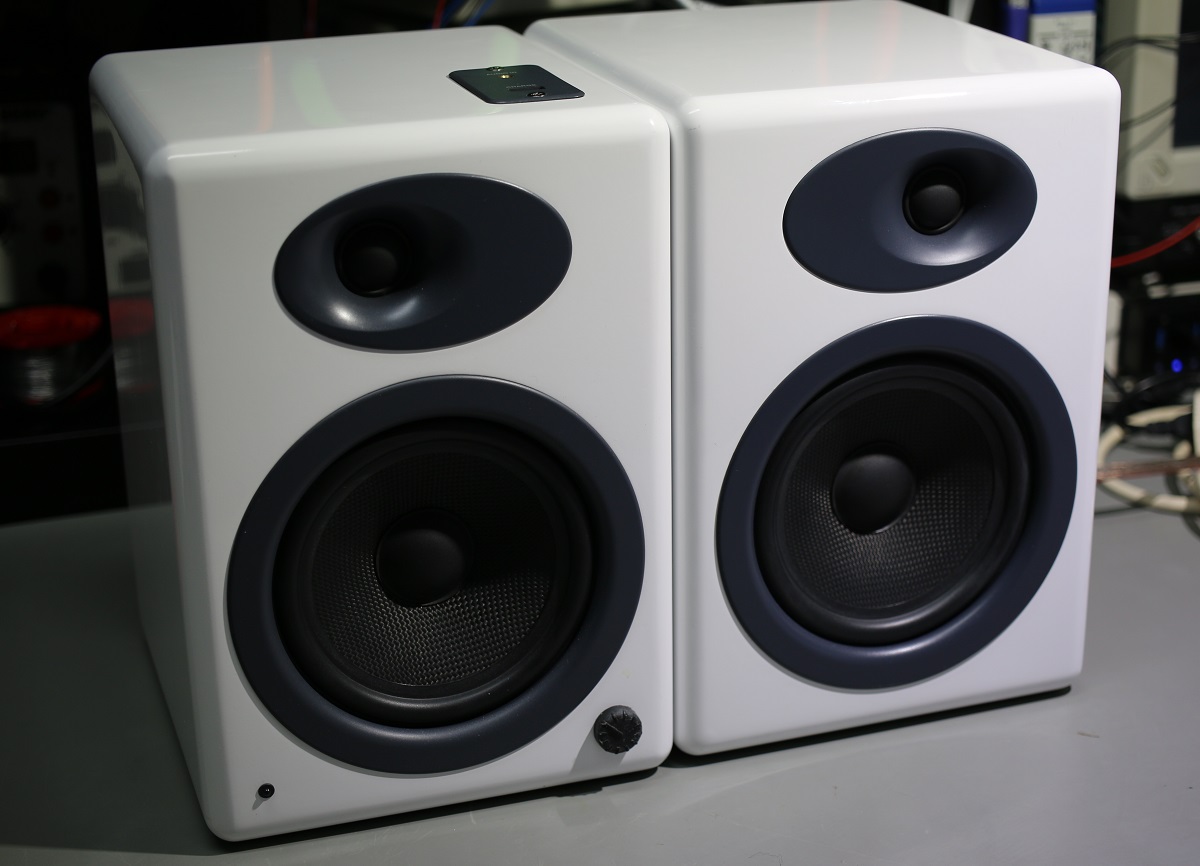
I started experiencing an issue with my A5 speakers: my right speaker was getting quieter than the left one!
I don't know about you, but for me this was one of these issues that would constantly annoy me as it progressively got worse.... there's so much an operating system's equalizer could do!
As customer support let me know that replacement parts weren't made anymore, I decided to sacrifice a Sunday afternoon to get to the bottom of things.
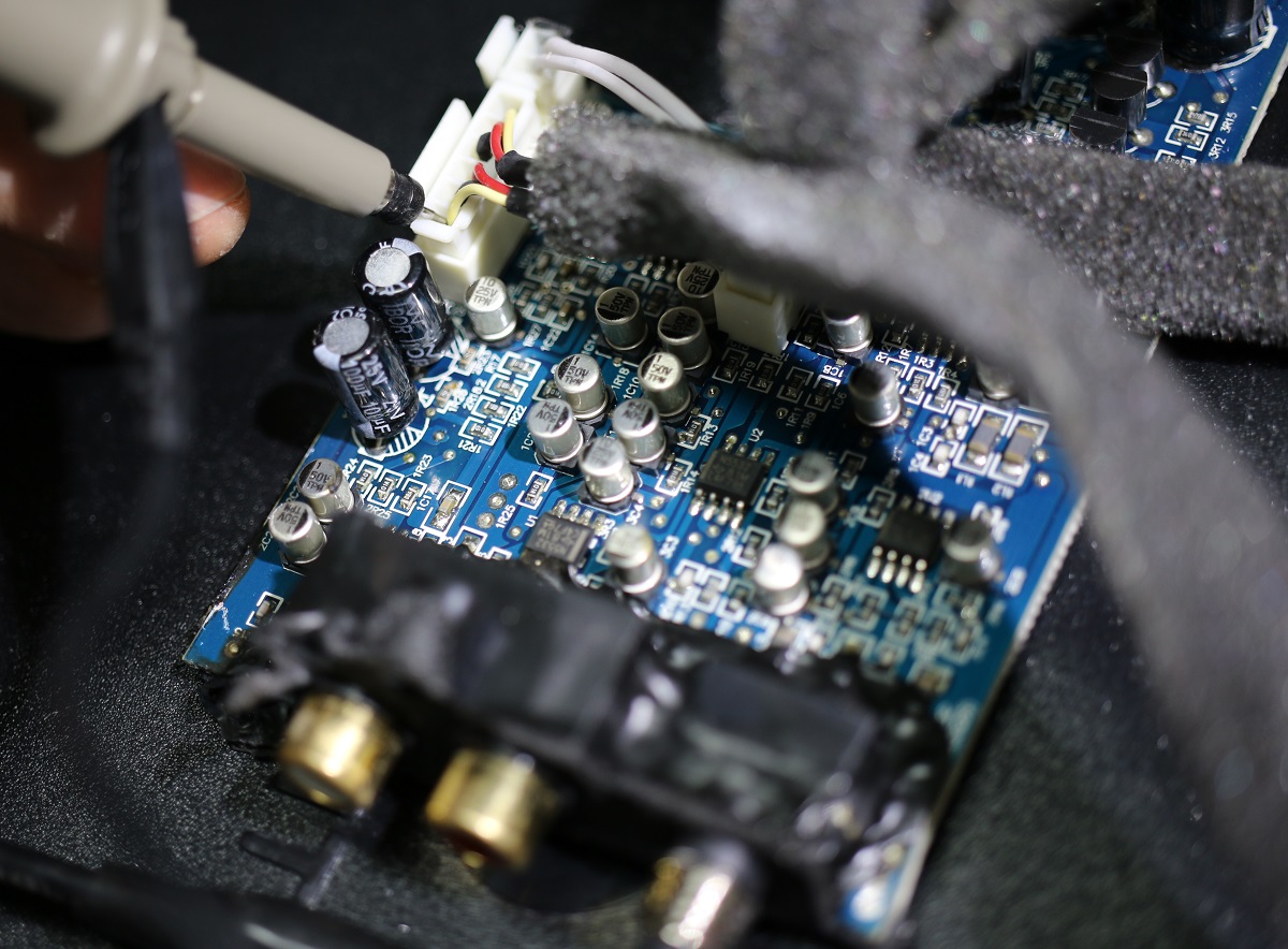
As you can imagine, the first step was to open the back of the left speaker, which contained all the electronics:
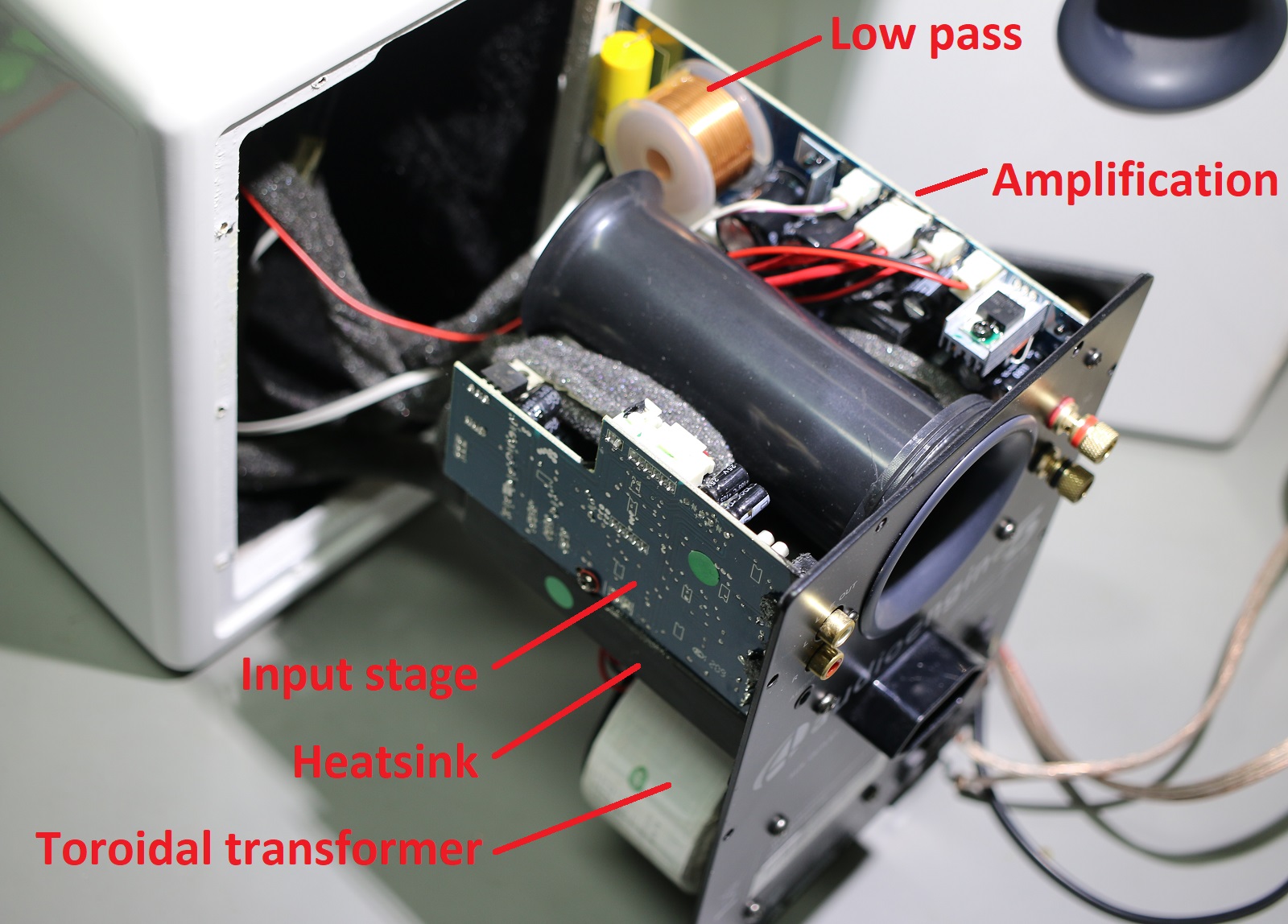
I was pleasantly surprised by the build quality: nearly all cables are surrounded by foam, all heat generating components are mounted to a big heatsink that is thermally connected to the speaker back-plate, and some kind of black silicon is used to make sure that no air can pass through the connectors holes (and dampen vibrations).
As the problem I was experiencing was a balance issue between the left and right channels, I started looking along the amplification chain for a place where I could probe both signals with my oscilloscope:
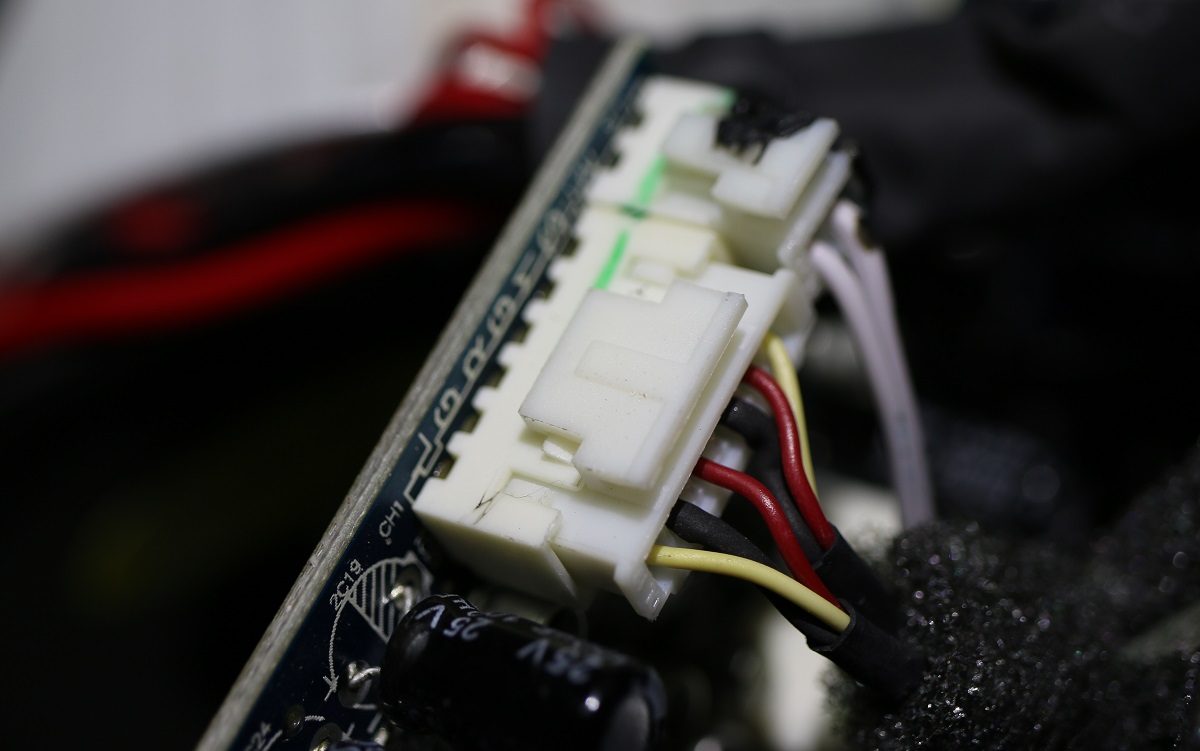
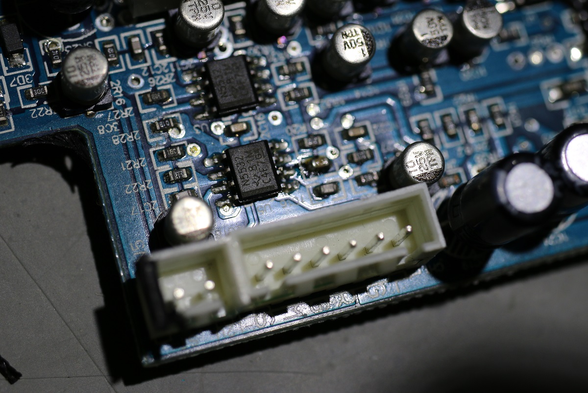
I then found this connector on what I called the 'input stage board', at the end of a cable connecting the latter to the 'amplification board'. Looking at the picture above you'll notice L/G/R markings, likely for Left / Ground / Right.
As to why there were 2 of them... I'm not fully sure but could guess it had something to do with the second input jack on the speaker (edit: they actually were mute & standby signals).
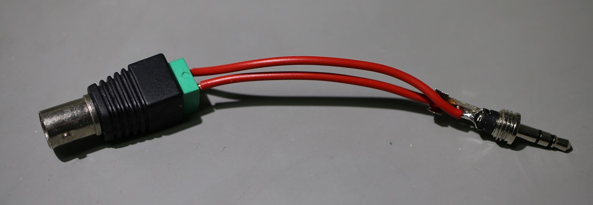
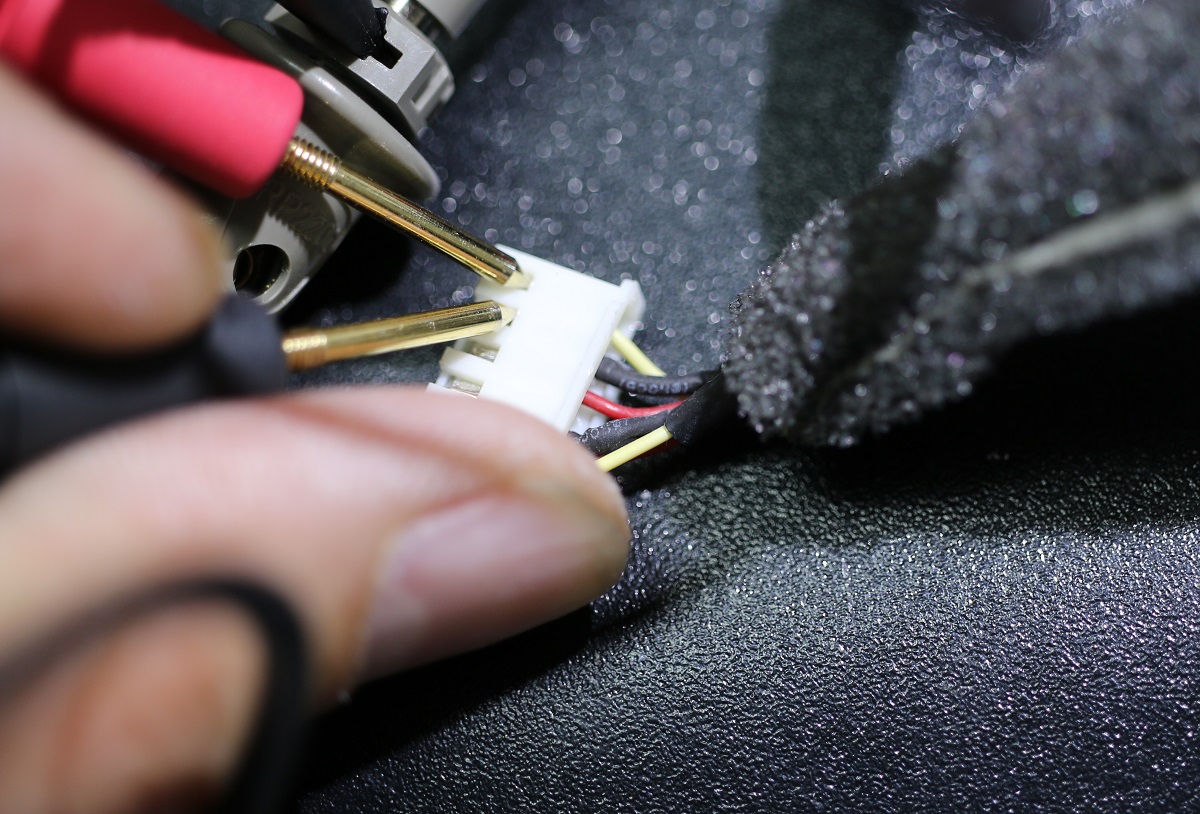
I then made the above contraption to feed a tone to the A5 input jack and checked for a volume imbalance at that connector's pins:
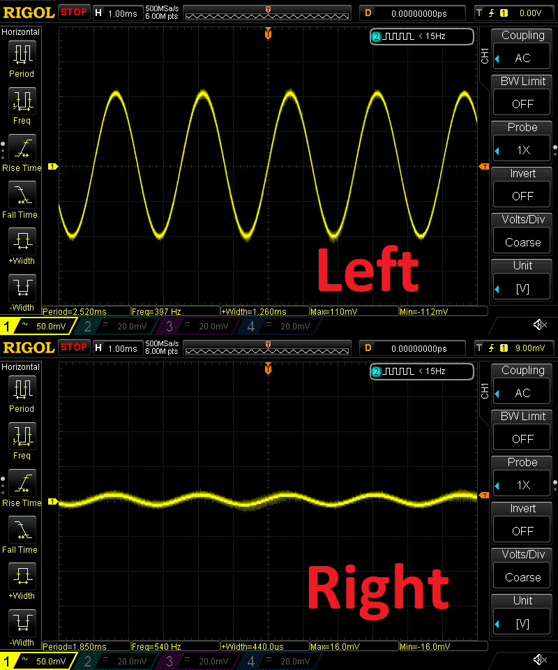
Success! I could definitely see different peak-to-peak amplitudes between the L and R marked pins.
I then disconnected the cable going to the amplification board and checked the resistance between each signal pin and ground:
47k for one pair, 15k for the other! The problem was on the amplification board... or so I thought.
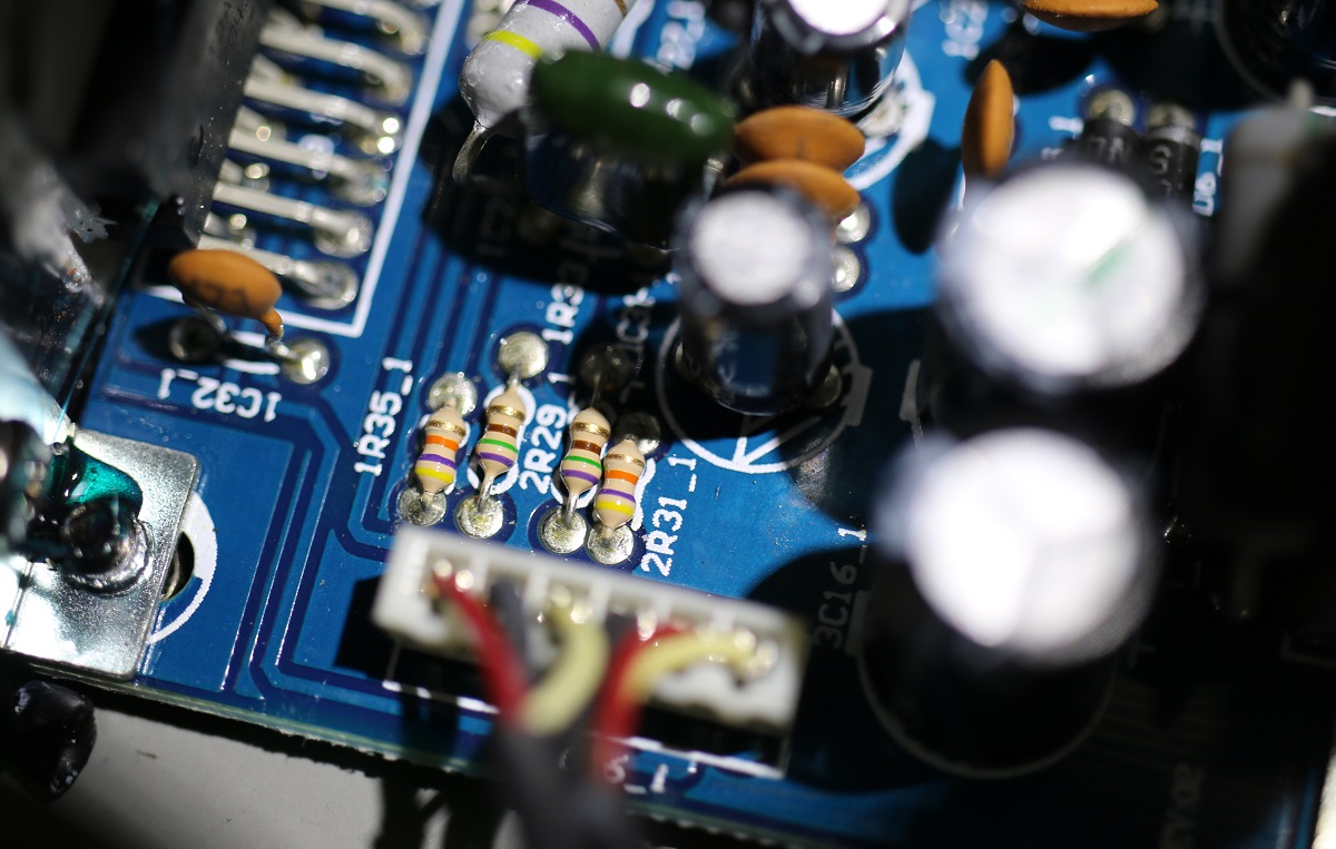
Following the L/R signals to the amplification board I was happy to discover the utter left/right 47k resistors, connecting each L/R input to ground. I confirmed my 47k & 15k measurement across each resistor, then removed what I thought was the faulty 47k resistor.
I measured the resistances again.... and discovered in disbelief that my 15k reading had become a 22k reading, even though the other resistor connected to each L/R input was 740k. How come?
Well.... I'm not 100% sure but my best guess is that a small voltage was still present at each node, which would confuse my multimeter.
I then turned my attention to the closest IC next to the connector on the input stage board. A quick google search revealed that the N5532 was a low noise amplifier and its datasheet let me know what its output pins were.
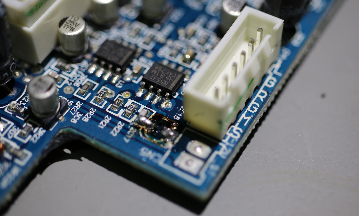
I confirmed that each of its outputs was connected (through passives) to each L/R connector pin I had previously probed, switched on the amplifier with a tone fed to it, and found that a capacitor seemed to be blocking one output signal! That's unfortunately quite typical as electrolytic capacitors age this way. A quick Digikey order and a bad soldering job later, I was ready to confirm my diagnosis:
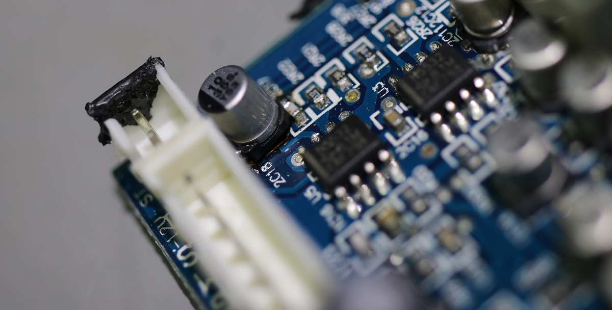
The capacitor replacement fixed the issue! But how to make sure it wasn't all in my head?
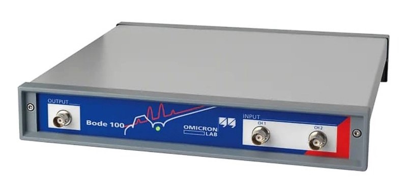
Well, why not check the transfer function between the jack input and the pads I was probing?
![]()
So it seems I definitely managed to repair my speakers! The gain difference between the left and right speaker is around .7dB, which isn't perfect but I'll live with it. You'll notice the large gain difference after 12kHz, but that didn't bother me too much as during testing I couldn't hear it (I'm getting old....).
An Even Better Conclusion
At the end of my debugging adventures I had a brain wave: if the manufacturer doesn't have the spare parts and doesn't sell this model anymore, why doesn't he release the source files?
I continued my support thread and got a nice surprise: Audioengine sent me the schematics!
You'll therefore find them below if you ever encounter an issue with Audioengine A5s...
a5_amplifier_board_schematics.pdf
a5_input_stage_board_schematics.pdf
Hats off to Audioengine!

Comments
thankyou, this article help me alot... my ae A5 got same problem
I have embarked on the repair of one Audioengine5 speaker for my boss. The 'input stage' as you called it seems to have a lot of corrosion on the board near a capacitor. Thus far, disassembly has been a nightmare lol. All connectors were glued, and even the PCB itself, while standing in the vertical position next to the heat sync, the bottom edge is also glued thoroughly to the frame of the box lol. I don't need anything, just wanted to voice my appreciation for this write-up and share a little of what I am going through now lol.
Thanks, my A6 has the same issue
I’m having a very similar issue with my A5+. I opened up the speaker and had a look at the amp and connections and all look clean but I’m somewhat of an amateur at this. When you say the capacitor was the issue, it’s not clear from the images precisely what you are talking about or what specific part you ordered and soldered. Would you mind clarifying? Ideally for a less experienced person! Thanks so much for creating this page!
@Sandy: the "round things" with a square black base are the capacitors that are likely to have failed. Unfortunately the only way to know if it failed or not would be using a multimeter :)
Hey limpkin,
I have a ~12 year old set of A5+ with what seems to be pretty much identical symptoms, this post has been very helpful, thanks! You inspired me to delve into a diag/repair. The amp has had daily use for over a decade, and aside from the right channel output, has performed normally.
The A5+ has a single board design instead of the split input/amp. Input section still uses N5532. Connector CN1 has LIN, SGND, RIN, SGND, RO and LO pins labelled. This section of the board has a lot of 10uF 25V caps - C4 seems to be the equivalent of 2C18 from the A5.
I removed C4 and it doesn't measure any capacitance - removed 4 more from the board to sanity check and they read ~7-8uF when they are still warm from being desoldered, but when they are at ambient temperature they read OL. I have tested warming them up again with ~100c air and they again read ~7-8uF, but immediately OL again after cooling. I don't know if this is a failure mode, not something I've experienced before. Regardless, I bought enough to replace all 14 caps.
Brand new caps are reading 10uF at ambient. Confirmed with multiple meters for sanity.
I was hoping for an obvious point of failure and quick repair but after looking over the rest of the board I found 4 bulging caps, so I'm going to replace all electrolytic caps while I have it open. Majority of caps are Chengx brand - none have leaked, the bulging ones have either failed an order of magnitude under spec, or read OL.
4700uF 35V x2 - 23mm D x 27mm H - critical diameter, 10mm lead pitch
All below are through hole, 5mm lead pitch on PCB
1000uF 25V x5 - 8mm D x 21mm H
22uF 50V x4
47uF 35V x2
220uF 16V x1
470uF 16V x1
100uF 16V x6
10uF 25V x14 - 4mm D, SMD
Will report back with results when I get parts delivered
Hey,
Happy to report my A5+ repair is complete and resolved the left/right balance issue. I did end up replacing all caps.
Majority of the non-bulging through hole caps were fine, a few were slightly out of spec. Around 10 of the SMD caps presented the same symptoms I previously described (OL when cold, ~7-8uF when heated). Given the enclosure gets pretty warm, I guess they just worked happily at operating temperature but I can't imagine they were performing well, or that they didn't have some impact on the sound.
My right ear is happy again, but I think overall there is some improvement - need more time to listen!
Picture of the whole assembly that comes out with the rear panel of the left speaker, with new caps fitted:
https://www.dropbox.com/scl/fi/km3b...
Where I would suggest people start looking if you're trying to apply limpkin's post to the A5+ board:
https://www.dropbox.com/scl/fi/byme...
Thanks again
oh wow, thanks for sharing rob and congratulations!
This is such a find! I just got a pair of A5s off ebay and the seller was 'they power up but ot tested' well, my risk failed. Blue LED power light does not come on, amplifier side speaker has cone pushed in on the woofer and muffled sound and left non amplified is not working - BUT, this post gives me a good feeling I can use some probling to get something
Only issue is if AE are not sending out woofers any more what I do with that - thoughts of a vaccuum cleaner on the cone may rip!