Radiation Pattern Measurements in an RF Chamber
By limpkin on Monday, October 15 2018, 16:30 - My Projects - Permalink
Very few are lucky enough to use such a piece of equipment... so I figured I'd share this experience with you!
Let me first start this write-up by apologizing for the lack of recent articles. As you can imagine, I've been fairly busy working on the Mooltipass ecosystem, and more recently on an upcoming wireless device!
Unfortunately this article is not going to be about its antenna (we're not there yet), but about ways to characterize antennas in general. Most (if not all) of the information below is over-simplified as my aim is just to give everyone a peek into the RF world.
What's an Antenna?
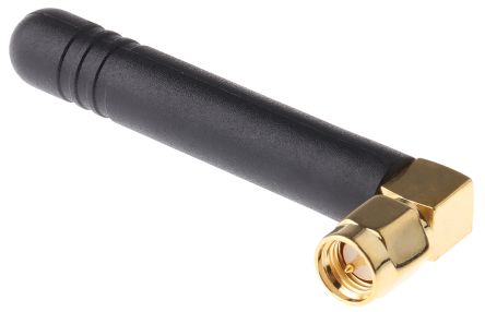
Let's take as an example the above standard Wi-Fi antenna. To make things simpler, we'll assume in the rest of this write-up that it is only used for transmitting RF. This antenna (and any passive antenna in general):
- converts an input power (fed though the SMA connector) into electro-magnetic waves (its main purpose)
- reflects some of the input power back to its sender: an unwanted effect caused by impedance mismatch
- absorbs part of the input power, due to internal losses
Let's imagine that you want to know how well an antenna is radiating. The very first step is to find out the frequencies for which this antenna is used so you can setup your measurement equipment.
In the case of Wi-Fi, this is fairly simple: a quick look on wikipedia tells you that there are 14 bands are located between 2.4GHz and 2.5GHz.
You can then measure how well the antenna is 'accepting' the power you're sending by using fairly expensive tools such as (Vector) Network Analyzers. It would typically show you something like that:
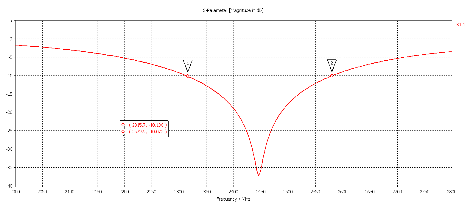
You can see that the amount of reflected power is at its minimum at the middle of the band of interest (2450MHz).
This is a good thing, as less signal is reflected more signal is likely to be transmitted over the air.
Vector Network Analyzers
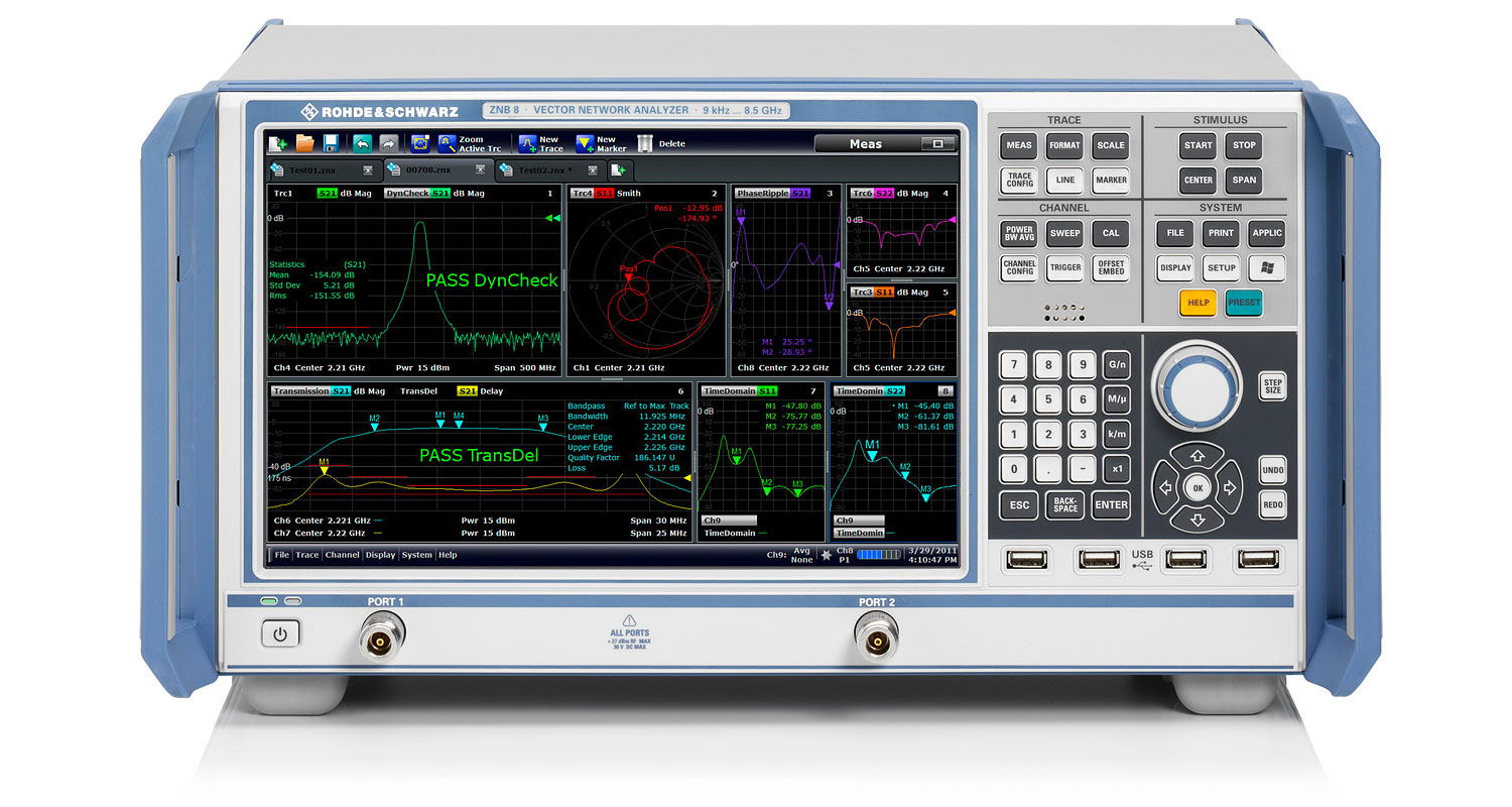
VNAs are cool devices. In short, they allow you to see the quantity of signal going out and back their 2 ports.
To characterize a passive transmit antenna you would therefore connect port 1 of the VNA to the input (RP) SMA connector and connect port 2 to a reference receive antenna. The VNA would then tell you (among many other things):
- the power reflection at the input, by measuring the amount of power leaving port 1 and the amount of power coming back into the same port
- how much power is transferred into the receiving antenna, by measuring the amount of power leaving port 1 and entering port 2
That last point is key as it gives you a feel of how well your transmit (TX) antenna can talk to the reference receive (RX) antenna. It is however affected by many things that can be 'calibrated out' except one: the environment you're doing your tests in.
In a standard environment, when the TX antenna is transmitting, the RF signal is being bounced and/or absorbed by tables, walls and any other thing in its way. It may also happen that something else in the room may be transmitting at the frequency of interest, making you believe that you're receiving more signal than you actually are. All in all that means you aren't able to know how well your antenna is radiating in a particular direction.
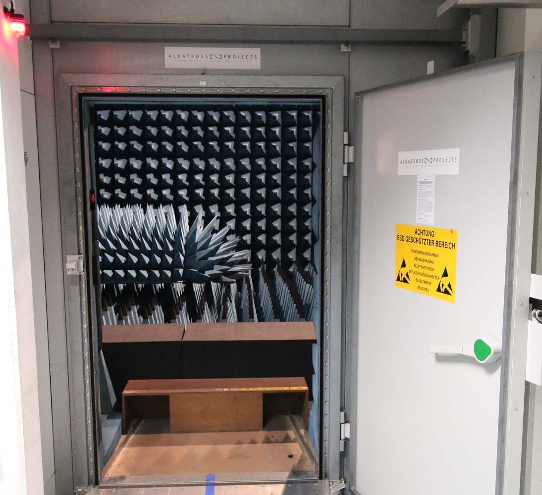
This is where anechoic chambers come in.
The Pyramids Room
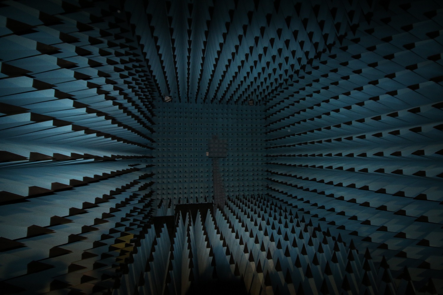
It does look that way doesn't it?
RF anechoic chambers have the following characteristics that solve all our problems:
- emitted RF signals don't bounce off the walls, all the cones absorb them
- RF signals from the outside don't come in: the chamber is a faraday cage
- these chambes are very silent (but that's just for me)
RF anechoic chambers are (really, really really) not cheap to rent. The one you see above is a chamber I had the occasion to do measurements in, located in Erlangen (Germany) at the Fraunhofer Institute.
In it, you simply mount your TX antenna (green in the picture below) several meters away from a receiving probe (the assembly on the right) and you'll then have the guarantee that the power received at the probe is the one sent by the TX antenna through a direct path:
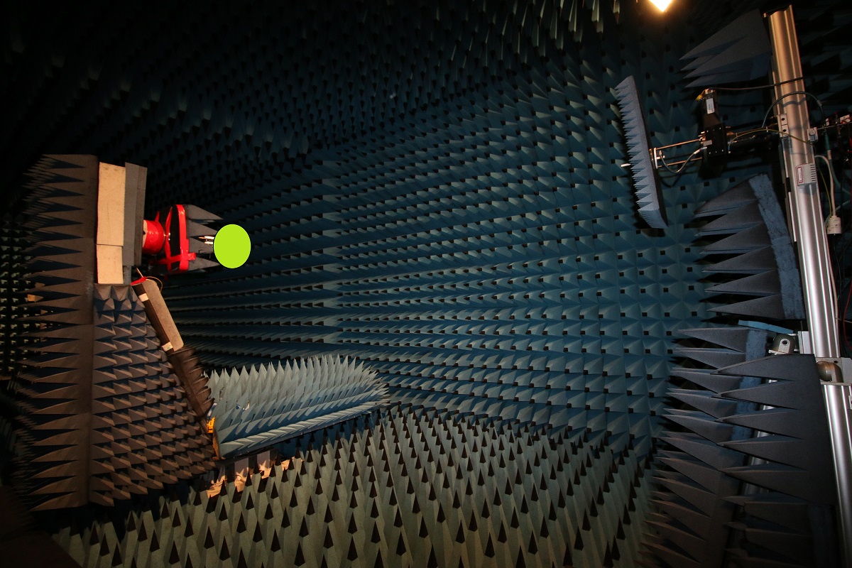
Obivously no devices except the Antenna Under Test (AUT) are allowed inside the anechoic chamber.
That means very long RF cables connect the antenna & probe to the VNA placed outside the chamber. In the picture above, the VNA was therefore measuring the amount of power transmitted by a test antenna when rotated at 90 degrees angle.
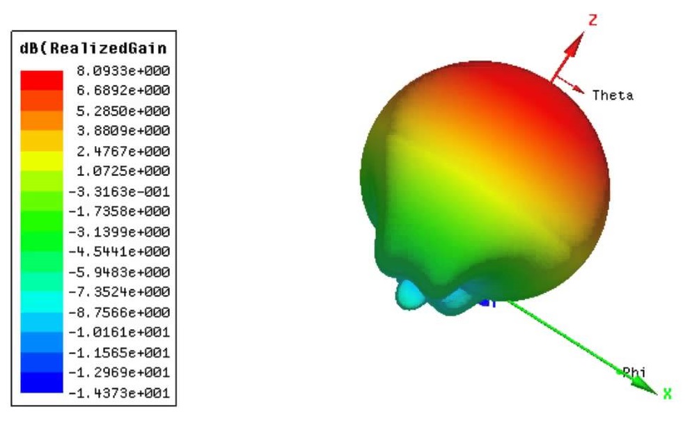
What's next? Well now that you can accurately know how much power your AUT is transmitting in a particular direction, you simply need rotate it on its Y & Z axis:
... in order to get recreate your radiation pattern:
Footnotes
I took a lot of shortcuts when writing the above paragraphs.
1) You may replace "TX" with "RX" and vice versa to change the characterization process for a receive antenna.
2) VNAs only output the power ratio between their port inputs/outputs, not the absolute power values.
3) Scattering parameters are therefore never explicitly mentioned. The "amount of reflected power" is indeed S11 and the "amount of transmitted power" is S21 using the setup described above.
4) the importance of dB scale instead of linear scale is left out, as it is a measurement 'technicality'.
5) the difference between near and far field measurements is not mentioned.
6) the complex calibration process and parameters setup of VNAs is skipped.
7) polarisation types are not mentioned.
8) the video above is sped up 10 times
9) the radiation pattern shown is one found on the internet
10) for obvious reasons, the antenna I used in fraunhofer is hidden.
