Project In A Day: When Is My Next Bus?
By limpkin on Sunday, July 23 2017, 20:36 - My Projects - Permalink
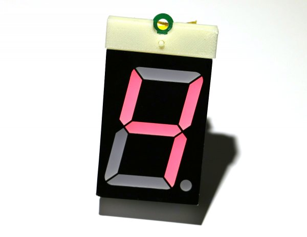
Made using only components from my stock !
Why This Project?
For once, this project was not for me... it was for my wife !
Every morning she takes the bus then train to go to work. If she misses her train, she has to wait for more than 30 minutes for the next one. Not missing her bus is therefore quite important.
Where we live every bus station has a display letting you know in real time when the next bus will be there. My first thought was to reverse engineer its RF signal but something easier then came to mind.
In the very same bus stations, a small QR code brings you to a web page displaying the very same "minutes before bus arrival"... HTML parsing therefore made more sense given that I was fairly busy with other projects.
What Did I Have In Stock?
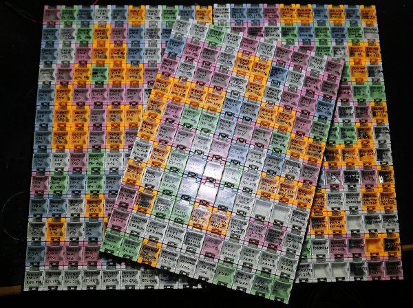
Every time I design a platform for a client or for my own projects, I order extra components (who doesn't, right?).
To display the number of minutes before bus arrival, I used a big 2.3" common anode 7 segment display:
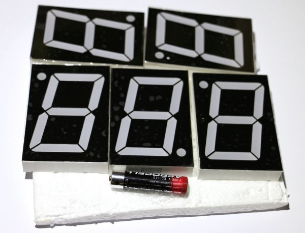
As you can guess, it doesn't use 2.5V per segment... but something around 7.5V.
I therefore needed a voltage step-up: the LM4510 was therefore found in my inventory.
Next thing: the power source. I really didn't want to have a power supply plugged 24/7 for this platform.
What I did have laying around was a ~5600mAh battery from a USB power bank whose charging IC had burned:
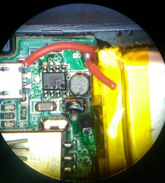
Yes, cheap USB power banks from China are a big no-no.
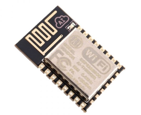
Finally, as the brain of this platform, to connect to my Wifi and fetch the bus time of arrival web page: the very well known ESP8266 was chosen, running NodeMCU.
The Schematics
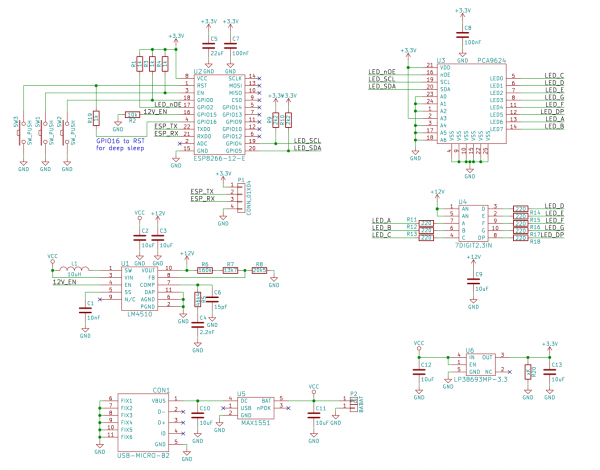
As previously mentioned, the LM4510 generates the 12V (I could have used a lower voltage) required by the common anode of the 7 segment display.
The PCA9624 then drives each segment cathode, and is connected to the ESP8266 through an I2C bus. Interestingly enough, it also has an enable input which can be used for blinking or even dimming.
A micro-USB connector (scrapped from a Mooltipass prototype) is used together with the MAX1551 to charge the Li-Ion battery. As the charge current is limited to 280mA... charging takes a while.
Finally, the LP38693 LDO generates the 3V3 required by the ESP8266.
The Board
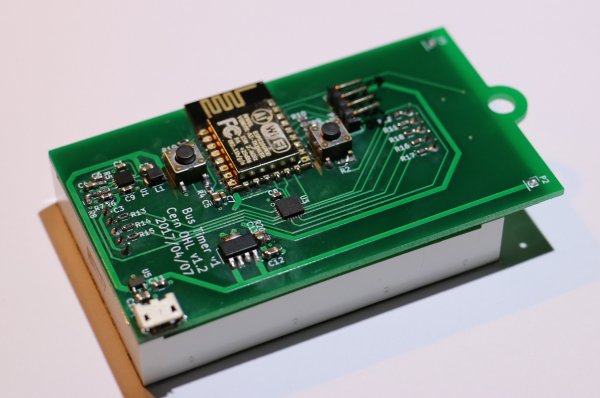
You can easily guess what each component does from this picture. The PCB has the exact same size as the 7 segments display.
The two buttons are used to start the ESP8266 bootloader while the 4 pins connector brings out its UART.

On the display side, you can notice that I 3D printed a "button extension". A simple press on it will wake up the ESP8266 from its deep sleep state to start displaying the time. As the LDO required a minimum 100uA load current, I actually had to add a load resistor!
The Source Code
As I said, designing the complete board and making its source code took me less than 10 hours.
NodeMCU definitely made things easy:
--bus_timer.lua-- Below: for each number (0->9) a boolean array specifying if we should set a non zero value into the pwm register, following the PCA9624 pwm register order
number_to_reg_val = {{1,1,1,0,1,0,1,1},{1,0,0,0,0,0,0,1},{0,1,1,1,0,0,1,1},{1,1,0,1,0,0,1,1},{1,0,0,1,1,0,0,1},{1,1,0,1,1,0,1,0},{1,1,1,1,1,0,1,0},{1,0,0,0,0,0,1,1},{1,1,1,1,1,0,1,1},{1,1,0,1,1,0,1,1}}
dash_reg_val = {0,0,0,1,0,0,0,0}
displayed_digits = {0, 0, 0, 0}
start_digit_reg_addr = 2
digit_address = 0x08
dot_shown = false
sda, scl = 1, 2
led_noe = 4
led_hv_en = 8
-- Below: time fetching logic
time_until_other_bus = 10
time_until_first_bus = 10
fetching_first_bus = true
fetching_done = true
displaying_first_bus = true
sleep_counter = 0

-- check for led controller
function check_led_controller()
	result = true

	i2c.start(0)											-- start i2c
	c = i2c.address(0, digit_address, i2c.TRANSMITTER)		-- see if something answers
	i2c.stop(0)												-- stop i2c
	if c == false then
		result = false
	end

	return result
end

-- write a register contents in a PCA
function write_reg_PCA(digit_addr, reg, val)
  i2c.start(0)
  i2c.address(0, digit_addr, i2c.TRANSMITTER)
  i2c.write(0, reg)
  i2c.write(0, val)
  i2c.stop(0)
end

-- update all segment registers inside a pca
function update_segment_registers(digit_addr, reg_bool_array, pwm_value)
	i2c.start(0)
	i2c.address(0, digit_addr, i2c.TRANSMITTER)
	i2c.write(0, start_digit_reg_addr + 128)
	for i=1,8 do
		if reg_bool_array[i] == 0 then
			i2c.write(0, 0)
		else
			i2c.write(0, pwm_value)
		end
	end
  i2c.stop(0)
end

-- display the number
function display_number(number)
	if number < 10 then
		-- display dot or not
		if dot_shown == true then
			number_to_reg_val[number+1][6] = 1
		end
		update_segment_registers(digit_address, number_to_reg_val[number+1], 0x10)
		number_to_reg_val[number+1][6] = 0
	else
		update_segment_registers(digit_address, dash_reg_val, 0x10)
	end
end

-- IO INIT
gpio.mode(led_noe, gpio.OUTPUT)						-- Led output enable GPIO2
gpio.write(led_noe, gpio.LOW)						-- Enable output
gpio.mode(led_hv_en, gpio.OUTPUT)					-- Led high voltage enable GPIO15
gpio.write(led_hv_en, gpio.HIGH)					-- Enable output
i2c.setup(0, sda, scl, i2c.SLOW)					-- init i2c

-- CHECK LED CONTROLLER
res = check_led_controller()
if res == true then
	print("LED controller here!")
else
	print("LED controller not found !!")
end

-- INIT LED CONTROLLER SETTINGS
-- Register auto-increment, normal mode, responds to all call
write_reg_PCA(digit_address, 0x00, 0x81)
-- LED driver 0->7 individual brightness and group dimming/blinking can be controlled through its PWMx register and the GRPPWM registers.
write_reg_PCA(digit_address, 0x0C, 0xFF)
write_reg_PCA(digit_address, 0x0D, 0xFF)

-- TIME FETCHING, every 5secs
tmr.alarm(0,5000,tmr.ALARM_AUTO,
	function()
		sleep_counter = sleep_counter + 1
		if sleep_counter == 240 then							-- 20 minutes of activity
			write_reg_PCA(digit_address, 0x00, 0x91)			-- pca9624 sleep
			write_reg_PCA(digit_address, 0x00, 0x91)			-- pca9624 sleep
			gpio.write(led_hv_en, gpio.LOW)						-- Disable output
			gpio.write(led_noe, gpio.HIGH)						-- Disable output
			node.dsleep(0)
			sleep_counter = 0
		end
		if fetching_done == true then
			if fetching_first_bus == false then
				http.get("VERYLONGURLHERE", nil, function(code, data)
						if (code < 0) then
							time_until_first_bus = 10
							print("HTTP request failed")
						else
							matches = string.match(data, '"time">(%d*)\'')
							if matches ~= nil then
								time_until_first_bus = tonumber(matches)
								print(string.format("Next bus #1 in %d minutes", time_until_first_bus))
							else
								time_until_first_bus = 10
							end
						end
						fetching_done = true
					end)
				fetching_first_bus = true
			else
				http.get("ANOTHERLONGURLTHERE", nil, function(code, data)
						if (code < 0) then
							time_until_other_bus = 10
							print("HTTP request failed")
						else
							matches = string.match(data, '"time">(%d*)\'')
							if matches ~= nil then
								time_until_other_bus = tonumber(matches)
								print(string.format("Next bus #2 in %d minutes", time_until_other_bus))
							else
								time_until_other_bus = 10
							end
						end
						fetching_done = true
					end)
				fetching_first_bus = false
			end
			fetching_done = false
		end
	end)

-- TIME DISPLAY, every 2 secs
tmr.alarm(1,2000,tmr.ALARM_AUTO,
	function()
		if displaying_first_bus == false then
			display_number(time_until_first_bus)
			displaying_first_bus = true
		else
			display_number(time_until_other_bus)
			displaying_first_bus = false
		end
	end)
A regular expression was used to extract the number of minutes from the web page, and if you look into the source code above you'll notice that I'm displaying 2 different times of arrival as my wife can use 2 buses to go to the train station.
The Source Files
This project was quickly done so I do apologize for the lack of documentation!
The kicad source files can be downloaded here.
Cheers!

Comments
Thank You, Mathieu, for very useful and valuable project!
Is possible to share the link of the bus stations web page?
Thank you for sharing :-) Where did you buy the stock containers you showed in first photo??
@ucasano : thanks! found them on ebay