The IN-9 Nixie Clock
By limpkin on Monday, November 1 2021, 20:43 - My Projects - Permalink
A 60 Nixie tubes contraption that I postponed for 5 years...
Introduction
It has been three years since my last blog post, and four years since my last published project.... time flies!
As you may have guessed, most of this time went into my family and the Mooltipass project, with its third device successfully funded through Kickstarter!
It's quite hard to find the time for the funky side projects that randomly pops into my mind when so many people like our offline password keeper. But I hope to make some time in the future for one off projects as they are free of constraints and allow their creators to truly go crazy!
Speaking about crazy.... this is the story of a PCB I made and assembled 5 years ago, but never got to put into its housing until now as I realized the original design wouldn't be pretty. Some of you may actually remember the high voltage power supply I made and wrote about, in which I had mentioned my intentions to drive many IN-9 Nixie tubes:

So... how many Nixie tubes was I talking about? Sixty of them, so I could make a clock!
With Nixie tubes now ten times more expensive than when I bought them, it seems I did well to purchase them back then (100pcs for $110!).
Only Nixie Tubes?
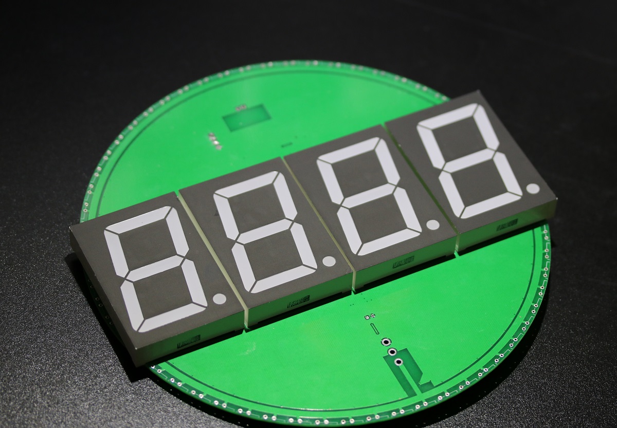
Nope! As my idea was to layout the tubes around a disc, I bought 2.3" 7 segment displays to put in the center.
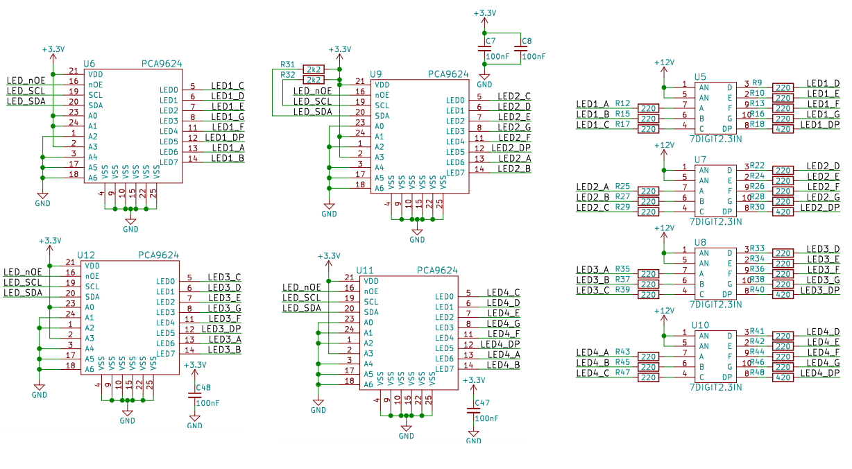
I therefore wanted to display the time using both tubes and 7 segment displays. To drive the latter, I just used some I2C PCA9624 LED drivers:
How to Drive That Many Tubes?

IN-9 Nixie tubes are current driven, which means the length of the glowing segment will be proportional to the current fed to it.
What's the simplest way to current drive something? By using a transistor driven by a filtered PWM signal:
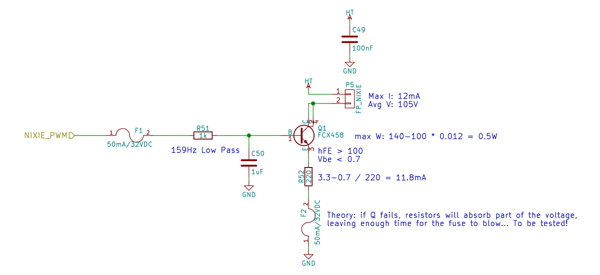
In the above circuit, a PWM signal is filtered using a RC low pass circuit, which is then fed to the transistor base. The transistor acts as a follower, setting the same voltage (minus ~0.7V) at its emitter.
As a resistor is present between its emitter and the circuit's ground, changing the PWM signal duty cycle will linearly change the current going into the resistor and therefore the current going through the Nixie tube.
But you may then wonder.... how to generate 60 PWM signals?
Yup... with an FPGA! I therefore wrote some VHDL to implement a 60 channels 14bits PWM controller.
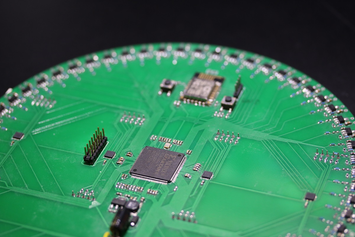
I remember it being easier than expected, and using a Spartan 3 with its embedded programming flash made the schematics very easy:
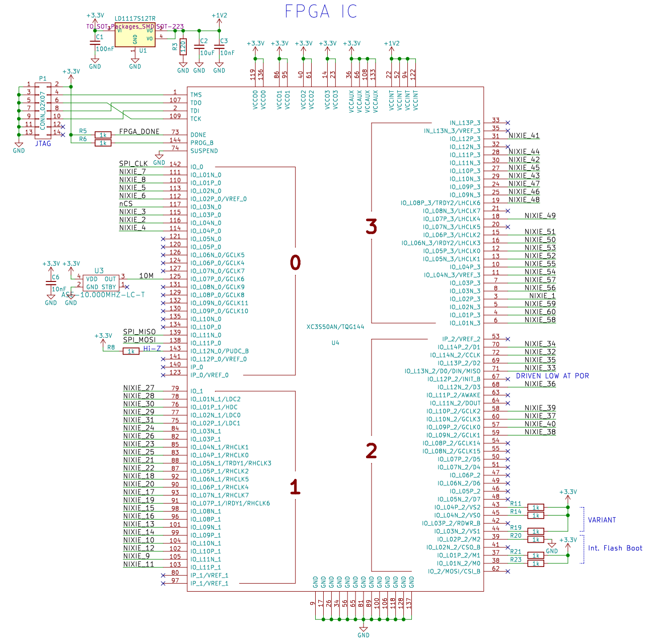
One 1.2V LDO, a 10MHz oscillator, lots of decoupling capacitors (not shown) and a few pull-ups & pull-downs... that's all it took! Finally, I also coded an SPI slave controller so the FPGA could be told how to drive each Nixie tube.
Which Microcontroller to Use?
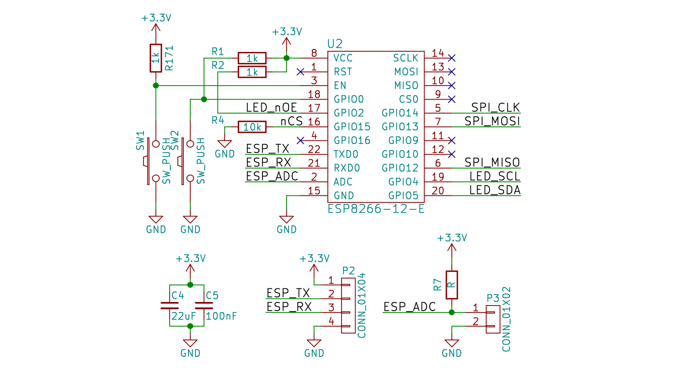
Five years ago the ESP8266 was all the rage:

I programmed it in Lua, running on NodeMCU as with only ~250 lines of code I could:
- connect to my home Wifi
- fetch the time from an NTP server
- configure the 7 segment display drivers using I²C
- .... and tell the FPGA how to drive each Nixie tube using SPI
The schematics for this part were also extremely straight forward:
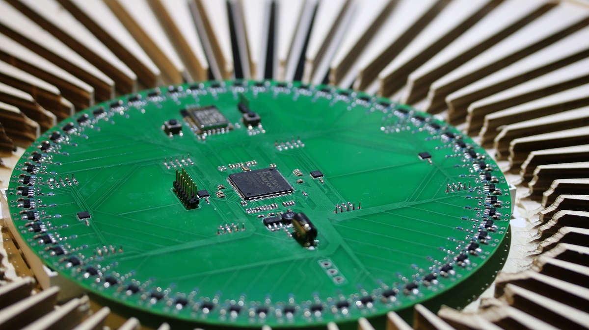
Putting It All Together
So I had designed the schematics and layout, assembled the PCB, written the VHDL & LUA, made sure it worked.... and waited five years to come up with a prettier housing.
You see, originally I had the stupid idea to have the Nixie tubes stick out of a central piece as spikes (like that).... but the prototype was truly awful.
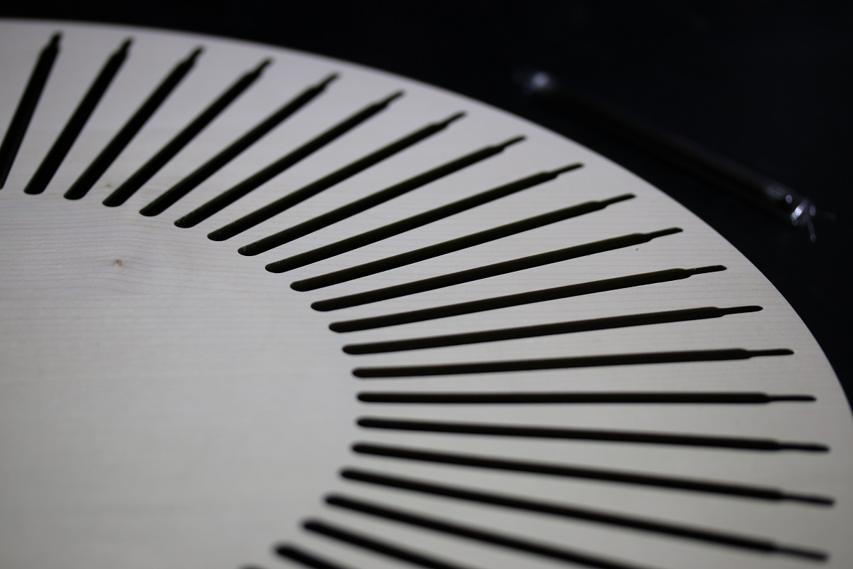
I then realized it would look prettier to integrate the tubes directly into a wooden part.
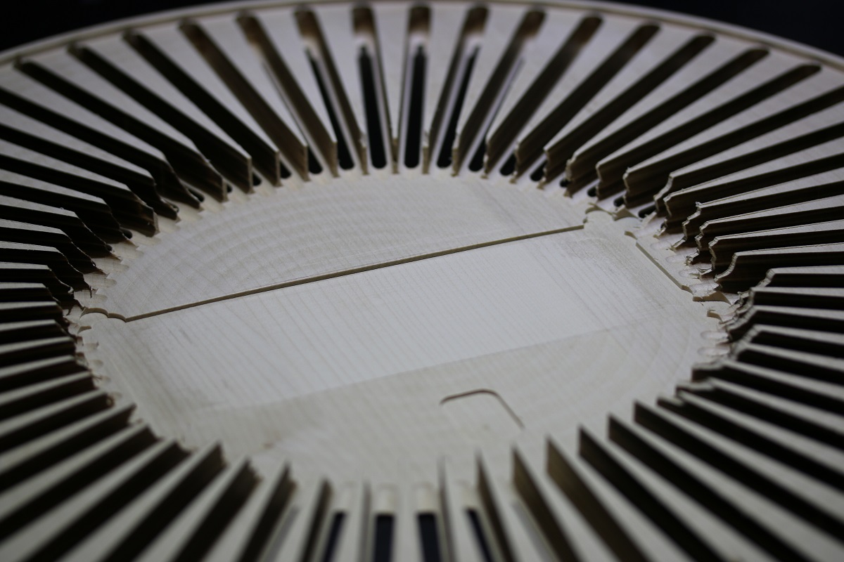
Designing the part, generating the G-Code that would be run on my father's CNC machine sure was fun.
As you can see above and below, the 7 segment displays are put in the machined pocket so their light can shine through the thin wood.
... while the nixie tubes rest inside their dedicated groves:
Layout and Safety
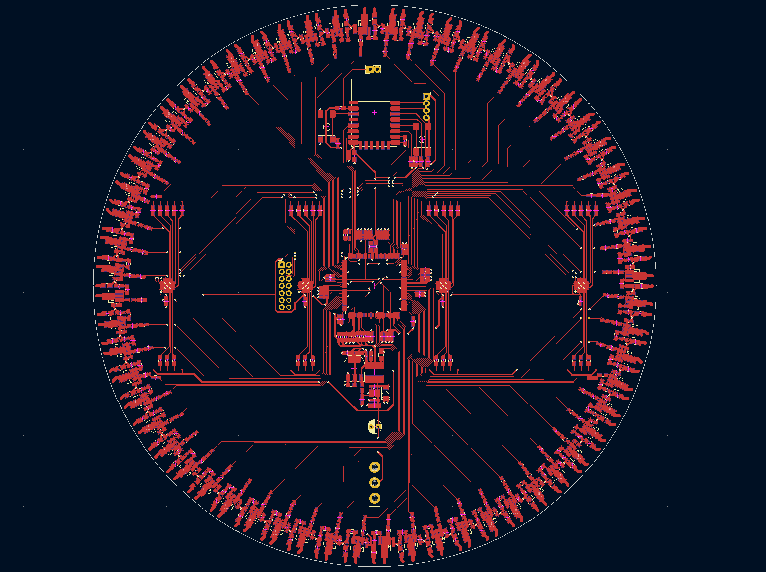
Ever wondered if Kicad's polar coordinate system actually is useful? I don't anymore, as it was extremely convenient to evenly space the high voltage transistor circuits.
Speaking about high voltage, 140V is no joke. Remember the fuses at the FPGA's and transistors' outputs? I blew several of them due to stupid mistakes, the highlight being: high voltage capacitors still charged, USB to UART adapter connected to my computer (therefore connecting earth to GND), soldering iron (connected to earth) soldering a nixie tube: nice spark, USB to UART adapter and ESP8266 fried. This actually happened twice....
Conclusion: do not forget bleeder resistors at high voltage power supply outputs.
In any case, these NPN transistors can fail in interesting ways, so the 50mA fuses you saw above will protect both Nixie tubes and FPGA (tested and approved).
IN9 Burn-in Procedure & Bring-up
Oh the nightmares, time spent and number of visited message boards...
Oddly enough, when trying to use something that hasn't been used for the last 30-40 years you may or may not get lucky. In my case I encountered two main things:
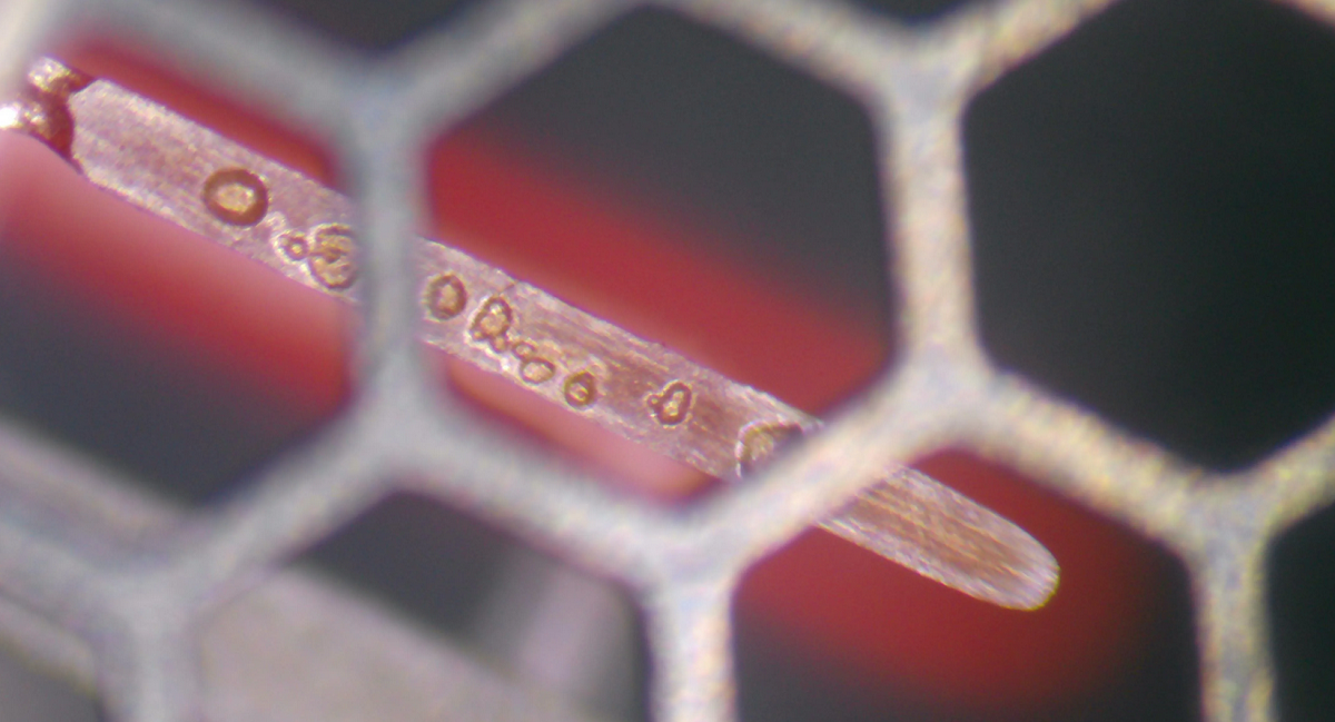
1) At first power-up, the light segment wouldn't go all the way to the top: this is normally fixed by a so called 'burn-in procedure' which seems to consist in powering a given tube at twice its rated current for a couple of hours. I instead simply left each tube running at max current (12mA) for around 10 hours.
2) Either at first light-up or during fast current changes the light segment would get unstuck from the bottom of the tube. Following some online posts, to get rid of that effect I setup a 1/20 duty cycle at a 50Hz frequency and let that running for 10 hours. However, in my experience it seems that IN9 tubes do not like sudden current decrease, which can severely limit what you can do with them.
This particular page was the most informative one on how to 'initialize' Nixie tubes, I highly recommend the read.
Finally, a given Nixie tube may simply be not good enough. I actually ended up replacing around 25% of the tubes I had first soldered.
Final Words, Pictures and Videos
Here are the tubes in action:
In the video above my nearby computer is actually running a python script which computes the FFT of my microphone output and then streams it to the nixie clock over Wifi!
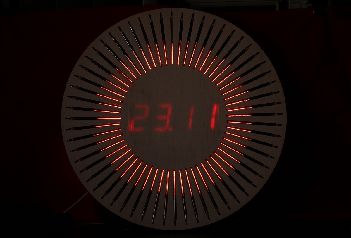
Below you can see the 7 segment displays in action... taking that picture was quite tricky as their brightness level is quite different than the tubes'.
You'll find all the source files made for that project on this GitHub repository. I'm still planning on improving the clock by adding some numbering on the central part and making some nice animations :).
Bringing Back Nixie Tubes to Life
While browsing around I stumbled on a video of someone who by himself brought back Nixie tubes from the dead and made a company out of it. Watch the video below.... it's mesmerizing.
