Easy-phi project: the rack and its backplane
By limpkin on Thursday, September 19 2013, 15:43 - My Projects - Permalink
So I'm sure that after the previous post where I presented the easy-phi project, you'd like to see the actual hardware. So we're going to start with the rack:
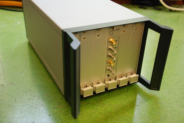
As a beginning, we decided to work on a frame that can (only) contain 5 electronics modules.
We chose a Schroff 28HP 3U rack, the Ratiopac PRO 3HE/28TE/315T to be precise. One HP (Horizontal Pitch) is 0.2 inch (5.08mm), and 3U means an approximate 5.25" (13.3cm) module height. The rack depth is 12.5 inches (31.5cm).
One module being 5HP wide, the 3HP remaining are used to display the rack status as well as measuring 'outside' light intensity.
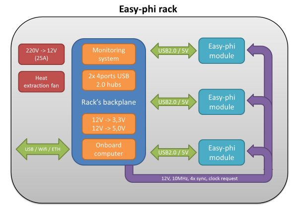
The easy-phi module specifications allowing a module to consume 50W of power, rack cooling is therefore essential. One fan extracts the air out of the rack from the back, which is why several openings have been made to the backplane PCB.
As mentioned in the project description, each electronics module has an individual USB connection. Consequently, the board includes 2x 4-ports USB2.0 hubs connected to the onboard computer. In the following picture you can see a Cubieboard, but we may switch to the cheaper Beaglebone in the future.
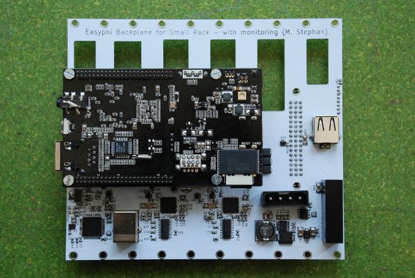
The rack sends a 10MHz differential clock signal to all modules, which can be overridden if a dedicated control signal is enabled. There are also 4 bi-directional synchronization signals which are common to all modules, pulled up to 3.3V by 2k resistors. The frame is powered by one 12V/25A power supply and two step-downs on the backplane generate the +5V (3A) and +3.3V (1A).
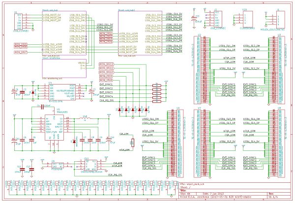
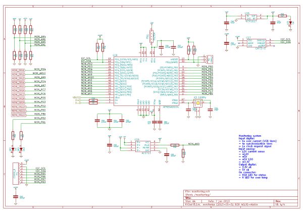
A monitoring system based on the ATMega32u4 checks the signal states, voltages, backplane temperature and 12V current consumption. The microcontroller enumerates as a virtual COM port so the Cubieboard can request the rack state at anytime. This system is using +5V generated from a LDO connected to the 12V. The ATMega is connected to two LEDs to visually check the presence of 5V and 3.3V in case the system becomes unresponsive.
Each 5V provided to the modules is controlled by current-limited, power-distribution switches connected to the USB hubs. If one module's 5V current consumption exceeds 0.5A, the module will automatically be disconnected from the USB bus.
All data signals are located at the center of the module's connector while the ground is at its periphery. This ensures that the first electrical contact made when plugging the module is the 0V. All signals are obviously ESD protected.
Anyway, I think most of the rack's features have been covered, but if you have any question don't hesitate to drop me an email! The official website is online and you'll be able able to download all the sources from there.

Comments
Nice article, Loved it will likely be subsequent more.