Electronics for a $7 USD doppler motion sensor
By limpkin on Friday, August 9 2013, 13:40 - My Projects - Permalink
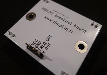
I had no idea that you could find this kind of motion sensors on the internet for so cheap... But they come with a catch: you need to design some electronics for them.
Editor's Note
A newer version of this sensor has been made can be found here.
The Doppler Effect
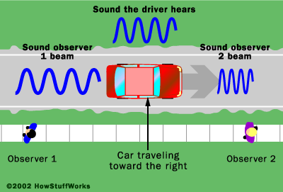
I'm sure you're quite familiar with the Doppler effect: you send an RF signal at a given frequency to a target, and if this object/person is moving the reflected signal's frequency will be shifted.
This is the reason why a fire truck's siren has a higher pitch when the truck is going towards you than when it is going away.
The HB100 Modules
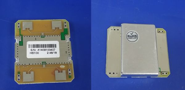
You'll notice the 4 patch antennas to send/receive the 10.525GHz. This frequency is really nice as the sensor will still work if there is some wood/plastic in front of it!
The HB100 outputs a low level voltage (few uV) whose frequency represents the speed at which an object is moving towards or away from the sensor. The output can be very noisy, so in addition to amplifying the signal, we need to filter out frequencies that don't match what we expect from ordinary objects.
The Amplification Schematics
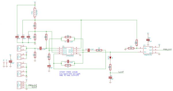
Let's analyze them step by step. U1 is a SOIC IC containing 2 operational amplifiers: opamp A & B.
The HB100's output is connected to P1 and C4/(R4&R2&R1) form a high pass filter. The signal at the opamp A positive input (IN+A) is centered at Vcc/2 because of this high-pass filter and the voltage divider made by R1&R2.
The opamp A, R5, C5, R6 and C6 form a non-inverting band pass filter circuit. It amplifies the signal at IN+A by 100 (R6/R5) between 3.4Hz (1/2*pi*R5*C5) and 72Hz (1/2*pi*R6*C6). The gain is 1 outside this frequencies, so the opamp A's output is also centered around Vcc/2.
The latter signal is then passed through an inverting band pass filter circuit. The gain is 121 (R7/R8) between 4.1Hz (1/2*pi*C8*R8) and 72Hz (1/2*pi*C7*R7). The gain is 0 outside these frequencies, but because Vcc/2 is present at IN+B the opamp B's output will also be centered around Vcc/2.
Here are the two types of bandpass filters presented in a better way (different component values are used):
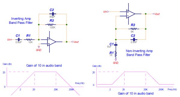
Anyway, you might wonder why the last amplifying stage's lower cutoff frequency is slightly higher than the previous'. This is made so to avoid amplifying the DC component as the band pass filter is not ideal (see above picture).
We finally amplified the HB100 signal by 100*121 = 12100... so you can guess that a lot of noise can be amplified.
To avoid that, FB1 removes the power supply's noise and the chosen opamps have a high common mode rejection ratio (CMRR).
Amplification Stage Outputs
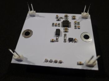
Finally, the amplified signal maximum voltage is detected using D1, R9 and C9. It is common to add a resistor in parrallel with C9 but as we are working with relatively low frequencies C9's leakage will do the trick.
To output a nice square signal, we use a discriminator (U2) detecting when the voltage crosses Vcc*0.55.
The Result
And there you have it: a nice Doppler motion detector!
But... What Speeds Can It Measure?
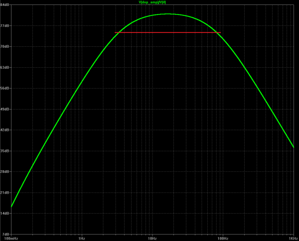
Unfortunately there is no easy answer. You can see above the simulated frequency response of the amplification schematics. The part of the green curve above the red line is between the 3Hz & 72Hz we mentioned earlier.
As you can see, speeds whose output are above 72Hz won't necessarily be filtered out!
Your speed measurement capabilities will therefore depend on:
- how RF reflective the moving object is
- how close to the sensor the moving object is
- if the sensor is at an angle with the moving object (see HB100 AN)
- if many moving objects are moving around the sensor (see radiation pattern)
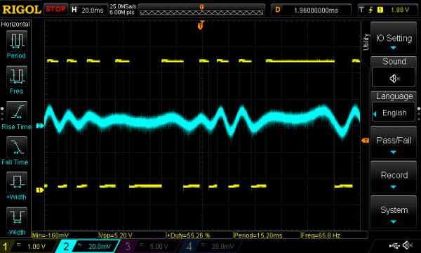
For information, here's an oscilloscope trace of the Doppler IF output when my hand is waving 50cm above it:
The Source Files
So here are all the files used to make this sensor. I recently migrated to KiCAD!
Bill of Materials Production files HB100 application note HB100 datasheet
If you don't have time to make one yourself... have a look at my store on tindie :-) .
Sample Code for Arduino
Due to popular demand, here's a very simple program that will output the object speed in your arduino terminal:
// Below: pin number for FOUT
#define PIN_NUMBER 4
// Below: number of samples for averaging
#define AVERAGE 4
// Below: define to use serial output with python script
//#define PYTHON_OUTPUT
unsigned int doppler_div = 19;
unsigned int samples[AVERAGE];
unsigned int x;

void setup() {
  Serial.begin(115200);
  pinMode(PIN_NUMBER, INPUT);
}

void loop() {
  noInterrupts();
  pulseIn(PIN_NUMBER, HIGH);
  unsigned int pulse_length = 0;
  for (x = 0; x < AVERAGE; x++)
  {
    pulse_length = pulseIn(PIN_NUMBER, HIGH);
    pulse_length += pulseIn(PIN_NUMBER, LOW);
    samples[x] =  pulse_length;
  }
  interrupts();

  // Check for consistency
  bool samples_ok = true;
  unsigned int nbPulsesTime = samples[0];
  for (x = 1; x < AVERAGE; x++)
  {
    nbPulsesTime += samples[x];
    if ((samples[x] > samples[0] * 2) || (samples[x] < samples[0] / 2))
    {
      samples_ok = false;
    }
  }

  if (samples_ok)
  {
    unsigned int Ttime = nbPulsesTime / AVERAGE;
    unsigned int Freq = 1000000 / Ttime;

    #ifdef PYTHON_OUTPUT
      Serial.write(Freq/doppler_div);
    #else
      //Serial.print(Ttime);
      Serial.print("\r\n");
      Serial.print(Freq);
      Serial.print("Hz : ");
      Serial.print(Freq/doppler_div);
      Serial.print("km/h\r\n");
    #endif
  }
  else
  {
    #ifndef PYTHON_OUTPUT
      Serial.print(".");
    #endif
  }
}

Comments
Thanks for sharing! Great place to start!
Hello,
Good job !
Which antenna did you use for RX and TX?
@Esteban : Hello, the antennas haven't been designed by me as I only made the back PCB.
I am trying to make this device using DIP components, but the chips are not made in the DIP pin package. What chips would you use instead or the OPA2365 and the MAX9031 that are available in DIP?
What would the use of the voltage output be? I have simulated a very similar circuit in Multisim, and get nice results with the square wave frequency output, but as I increase the frequency the voltage decreases, and I'm not sure that should be happening.
Thanks!
@SD, I used OPA2350, which is available as DIP and has a very similar spec.
@rayui : Sorry, they'd actually be confused...
@rayui : that'd be possible. However given that you're dealing with GHz signals that won't work...
@rayui : I mean that you won't be able to transmit a high impedance GHz signal for more than a few cm :)
@rayui : this provides a nice introduction: http://en.wikipedia.org/wiki/Transmission_line
Thanks for offering this nice device! Do you know the maximum velocity this device will detect? Or the smallest flat object it can detect? It made me think of an application in which I want to monitor the vibration of a beam or plate.
Thanks!
@Hal : I honestly have no idea, sorry!
I think you answered this above, but I'm curious as to whether this device could possibly measure distance to an object (moving or static), rather than simply velocity?
I bought an HB100 recently but i haven't had a chance to incorporate it into any of my projects yet. Any way i was wondering if you sold just the "breakout board" by itself as i already have the HB100. Thanks!
@Matt : The measurement wouldn't be reliable indeed.
@Cody : Sorry! I only sell the complete assembly.
What kind of range would this have? i.e. would it be something like 60 feet or 60 inches?
Would it work well if the object you are measuring goes across the front of it? (rather than coming directly at or going away from it). e.g. put it out the window of your house to measure the speed of cars going by.
@Brian : Something around 20 feet depending on how big the object is. I'm quite sure it wouldn't work very well if it went across the front of it.
Hi... I recently purchased this module (haven't received it yet). A couple of quick questions:
1) Do you have a document explaining VOUT and FREQ_OUT based on the relative speed of the two objects. In other words, if I connect the VOUT to an ADC, what would the number indicate vis-a-vis the frequency shift? Same for FREQ_Out, if I connect that pin to a GPIO and time the pulses, what do the numbers mean? I need to be able to measure positive and negative frequency shifts. Thanks
@Afshin : Hello, thanks for your purchase! VOUT is proportional to the amount of reflected energy so you'll have to experiment. As for the FREQ_OUT ouput, I invite you to have a look at the application note.
Thanks very much for the response... To let you know, I would like to ascertain the speed difference between the moving object and the module... as such, does the FREQ_OUT have indication to that effect?
@Afshin : in theory yes... but I doubt that will be the case in practice, depending on your setup.
Did anyone overhere succesfully connect this sensor to an Arduino or Raspberry? I am very interested in the wiring you have done to connect it. anyone got some pics or a youtube link?
this device can be used to measure tennis ball speed ( with a speed exceeding 220 km / h )?
I did some study on this, but I don't want to shortcut the sensor so a confirmation of my wiring would be nice.
I came to this Arduino connection:
http://nl.tinypic.com/view.php?pic=...
@Valdomi Land : Unfortunately no!
@Aux : as long as you correctly configure the IOs you should be fine!
On Valdomi lands question and answer to it:
Do you think it is impossible to change filter component's values to measure faster objects speed? Is there some limitation in opamps or HB100 modules performance or in your filter design?
@Robojuchen : It is of course possible to change the filter components values, as long as you don't exceed the opamp GBW product :)
Me again, I managed to connect it the sensor to an Arduino Uno
Currently I am using Firmata and ArduinoScope to grab the data from the device.
http://nl.tinypic.com/view.php?pic=...
Any help on the next step would be appreciated. What I try to achieve is to get the speed of the object that is passing the sensor.
I guess I need to get raw data from the device so I can process that into speed.
Hi! nice work! Is the output of the square pulse train fully compatible with the arduino DUE analog input? thanks!
@oscar : Hello Oscar! You will need to use a resistor divider to bring the voltage to 3.3V.
Hi, great work.
how small at what velocity objects can be catched?
pellets? bullets?
thanks
Before using hb 100 , its library should be bulit in arduino or not ?
Thanks
@Bero : Hello there! Unfortunately I don't think this sensor will work with the small objects you describe.
@Arslan : I'm not sure to understand you...
Hi. I bought a module from you on tindie. I can't get it to behave the way you do in your video. The voltage output goes to Vcc immediately when something is moving in the room. That is, it does not give an output proportional to the distance like in your video. Any suggestions?
@nic : From what you describe it seems you are measuring VOUT and not FOUT?
yup. Measuring Vout, isn't that what you are doing with the yellow graph on your oscilloscope? The green one must represent the speed of the object (frequency output)? I can't get anything similar to your yellow graph from VOUT. So what is your yellow graph representing?
@nic : Yellow is indeed VOUT. Are you sure the HB100 is not affected by reflections inside the room? Ideally there shouldn't be metallic objects close to it.
I tried to do a test just like your's (just did it). I can't get a result like you show. I have tried to move to another room, no effect. It just climbs up to max voltage whenever something is moving within two or three meters. If i stay still, then it goes down to around 2.5V again (very very slowly). It does not behave like in your video above at all. I feed it with 5V, measure it with an oscilloscope and an arduino analog input. Tried with 16mm of wood in front of the sensor also, same result.
@nic : For information all the HB100 sensors are tested like in the shown video :). How is the HB100 fixed to its support? It should be as close as possible to the table edge.
If the sensor is pointed down at the road surface, say at 30 degrees, would it detect road speed (with angle correction in software)
@mga : Hello there, it would indeed!
@Aux : Did you get the sensor to work with some arduino code and got valid results??
Best regards!
-andreas
Hi Limpkin, I bought your sensor, and I made myself the board with your diagram, but it doesn´t work as yours, I changed the comparator for this: GENERAL PURPOSE COMPARATOR, SINGLE, 0.2 US, SOIC-8(LM211DT), The Diode for this: DIODE, SCHOTTKY, 1A, 40V(1N5819HW-7-F), the R4 330k resistor for this: MC01W08051330K, and the FB1 for this one: FERRITE BEAD, 0.35OHM, 400mA, 0805(BK2125HM102-T).
Does it really affect the performance of the sensor??
@Nightmare : you should be good!
Hello everyone,
right now we are busy with a school project. We want to build a velocimetry with an Arduino and a HB100. Unfortunately we noticed that the HB100 only measures frequencies in a ~20cm range. We tried different ankles and also tried to isolate with a tinplate which we placed around the sender, the resulat was the same.
Any ideas, any experience with that kind of problem?
Many thanks in advance.
Have a nice day!
Hello There,
We are using a normal Arduino uno and the HB100 to detect the speed of bypassing cars on the street in front of our school, but we have a small problem with it:
By now we have everything set up and working (nearly) properly - the arduino gets a signal by the hb100 and uses a lcd to display the results (-> the speed). Our problem with the hb100 seems to be the range: It seems to retrieve signals within a range of only ~20cm. We already checked all connections and everything seems just fine. We also tried to use a tin plate around the hb100 to isolate signals from other directions, but that didnt help either. Do you have any idea what could be wrong here? Since we want to detect the speed on a normal street,we need a range of at least 5 meters.
Thanks in advance for your time.
@Redman : Did you purchase the HB100 from me?
@Alexander S. : Hey Alexander, did you purchase the HB100 from me?
I've clocked my own car and a few vehicles on a public road with Doppler audio recordings from an HB100, using an Arduino UNO to average through the noise, recognize a target, measure the shift, and calculate the speed. I noticed this post while Googling for the HB-100 spec sheet. I've had some success, but work on it only intermittently, so I redecorated my Arduino code with explanatory commentary and posted it on GitHub along with some audio files and plots to demonstrate the algorithm. Its accuracy is uncertain, but it appears to be close. Your results may vary and you're on your own, but I hope you find it helpful.
Cheers!
@Dave : Thanks a lot!
Concerning use of this particular module in a car - as a former Air Force Radar Tech, I've also had what used to be called a First Class Radiotelephone License with Ship's Radar Option for almost 50 years. I'm well aware the module is not intended for use in a vehicle. If the AM proto works, I'll try FM and install an FCC Type-Approved module.
I did kluge it inside the rear bumper of my new SUV. It was virtually overloaded by a nearby metal object, so I moved to a quieter location. Now it sees the road surface and/or rear tire. It does have an extended horizontal pattern.
I've pointed it straight up and it still sees either the road or tire. It may be backscatter. I've selectively lined the bumper with pieces from a heavy duty Aluminum oven liner. Still sees the road or tire. The antenna may also have a backside sensitivity, which I haven't yet foiled.
May be time to purchase or kluge a feed horn.
Regards,
Ron
@Ron : thanks for the feedback!
Is it possible to detect motion behind a wall or must it within sight?
@Joseph : I'm guessing this would depend on what the wall is made of.
Great writeup. I'm working on a project utilizing the HB100 and unfortunately, bought the thing before I realized it may not work exactly as planned....
Would the antenna array still receive signal if using multiple HB100's without applying power to the unit? Meaning, if I only amplify the IF output, without applying 5v to the unit, would a signal be adequately produced? My plan was to use three HB100's to track an object.
Otherwise I may need to look at other units elsewhere.
Have you played with Pulse-wave at all with the HB100?
So far I have just made a single sided Eagle layout for the mini amplifier, but I think I need to redo it for signal separation and noise, the more I read about these types of units.
@Andrew : The unit needs to be powered as the antenna signal passes through a signal mixer. I didn't play with pulse wave.
i would like to know the V_Out, is it mean Distance the target?
if the target far from the doppler 1m and has frequency 20Hz and if the target far from doppler 5m and has frequency 20Hz. Then the Value of V_Out will be equal or not?
Thannks
@Surachate : VOUT is proportional to the amount of reflected RF energy.
Hey, I bought one of your modules last week and I just wanted to start off by saying great work!
But now I am trying to make a pulsed doppler separately, and even when I follow the application notes, the output still seems to be continuous wave doppler.
Have you managed to make one using the hb100? Is there any way to improve the schematic on the application notes?
@Mario : Hello Mario! Unfortunately I've never tried pulsed mode... but I don't see why its mode of operation should be different than continuous wave doppler.
@Dave : May I have your email address or contact information? I don't know how to contact you in Github but here is my account: https://github.com/Nigthmare
@Aux : Would you please share the wiring diagram of this sensor's backpack with arduino uno?
would you please give me some guidance in wiring diagram of this sensor to arduino uno?
I am using it in my Final Year Project to prevent accident.
Hi, this is great. I have built this circuit but using an LM358 and a MCP6541T-E comparator instead. Do you think this should work okay? It is not totally built yet I am waiting for my ferrite filter to arrive.
Also to increase CMRR could I just use voltage followers and connect them like as in an instrumentation amplifier?
I'm referencing you work as my final year project and the chips you suggested using were too expensive so I had to change them. I hope I picked some that will work. Even if its only slightly as good as yours.
Thanks
@Richard : Please check the GBW product of the LM358 and make sure it's big enough. Also note that instrumentation amplifiers aren't made to provide lots of current.
I know the HB100 works well to measure a motion, but what about the speed?. Can the HB100 measure speed with an acceptable accuracy?.
I want to use a HB100 to measure the speed of a open channel water flow. My idea is to set the HB100 with some angle above water (around 2 meters).
I'll appreciate your reply and advice.
@ctorregrosa : the HB100 is actually made to measure speed! It is therefore possible but you'll have to take that angle into account in your speed calculations.
hello.
I recently bought HB100 from you.
it works well for walking speed.
I want bit faster than its normal speed.
so, according to your page, changing R6 and R7 makes filter range. right?
I changed the R6 and R7 into 7K ohm.
it didn't work, FREQ out is keeping high.
my question.
am I right? changing R6 / R7 makes different frequency?
also
how fast can it detect?
thanks a lot.
@akiron : Hello there! 7k is way too little, as the GBW product of the OPA2365 isn't high enough! As for the max speed, it all depends on how big the object is. As you can see the RC filter isn't a perfect one so you may still detect relatively high speed when objects are close.
hello limpkin.
thanks to answer my question.
right I understand 7k is too little.
what do you think, how far can I try?
how about 100k ohm?
@akiron : I'll let you do the maths and check that ;), all the formulas are on this webpage after all!
Hello Sir! I am very interested in your product. I have a need to detect motion only (not speed) at range from 0~40 feet. I am deciding between your device and a unit made by Parallax. How do they differ and would yours suit my needs better?
@HM50 : Well my module directly outputs the frequency and reflected RF intensity while the parallax only has a detection output...
Sir,
When I connected the IF pin to arduino, I got a 0 and 1 intermittently, if the voltage is in uV range, how is possible that i get 0s and 1s What is the use of Vout in calculating the speed? Is it possible to extract the frequency using FFT?? I'm quite new at this... Please help if possible..
@Nipun : the IF output needs to be amplified! My guess is that you're getting outside noise. FFT is indeed a way to measure speed, but on the amplified output only.
Operating range is up to several meters?
@Asgari : 10 meters at least yes!
Hello, it would be possible to detect whether movement is toward or away. Thank
@Compi : Of course! By simply looking at the VOUT output you'd see if it is decreasing or increasing.
HI. sorry, C5 it is 4.7uF no 4.7nF
I wonder if it's possible to use a raw HB100 without the breakout board and do the filtering in software, similar to how SDR is done. Given a fast enough ADC sampling the IF voltage, would software-based signal filtering be an option with this sensor?
@yuval : I don't think you'd be able to find an ADC that can measure such small signals... RTL-SDR dongles all have a LNA for a good reason ;)
@Compi : In my board VOUT is directly proportional to the amount of RF waves reflected to the sensor.
Hi limpkin
I'm really interested but i would like to know how i can plud this with arduino to make a radar
Maybe if you have an exemple of code
HAve a good day
@Jingatak : Hello! Any frequency counter sketch will do :).
@limpkin
I want to do a radar which can detect a tennis ball do you think it's enough precise?
And can you help me for the connection for arduino and the code i'm not that good so if you have some advice it would be very cool
@Jingatak : Please note that the sensor can't measure high speeds. You may have a loko at http://interface.khm.de/index.php/lab/interfaces-advanced/arduino-frequency-counter-library/ for the library.
@limpkin
What is the maximum speed?
@Jingatak : it all depends on how close the object is. I'm guessing that performances won't be great for a tennis ball.
Hi limpkin,
I need to detect high speeds , like vehicles passing , would it work with this module?
thks
@Fred : It all depends on what you call "high". It'll also depend on how close the vehicles are.
hello, how does a low GBW of the amplifier affect the performance when compared to a high GBW?
@Richard : Well you'll effectively reduce the maximum speed you can detect.
Hi, I bought your board, and foolishly powered it briefly with reverse polarity (perhaps for a second or so). The output on a scope looks to be fine for both frequency and voltage, The pulses are still nice and square ~0-5V, and a hand-wave signal had pulse widths in the order of 10ms.
Do you think the board is likely to have survived?
@Kevin : you should be good ;)
Hi limpkin,
can I measure the speed of a tennis ball (while serving) with your HB-100 breakout board
(and raspberry pi or arduino uno)?
@bubble : Hello there, please see the dedicated paragraph in this article...
Really nice finished design. Do you think the mixer can be swapped out with a side band rejection mixer to distinguish or isolate positive or negative Doppler frequencies?
I want to make this radar for c band and to process the signals for object detection for longer range. Can i connect bigger antennas for this module?
Hi Limpkin, Great work. Can you tell me who much current your board draws please? I would like to build one into a battery powered device which needs to be very low power. Also does it need any warmup time when first powered. One method for me to reduce battery consumption would be to only turn it on for a short period of time every second or two to detect if any motion is present. I have experimented with the Parallax version of this but their amplifier circuit draws 3 mA even with the Microwave turned off! Thanks
Nick
@Nick : Hello! It draws around 50mA. I unfortunately can't tell you about the activation time, but that's what you'd need to do indeed!
@rakesh : I'm affraid that is not possible due to the required impedance matching.
@Dole : I'm affraid not!
I've used a LM324 for this circuit and it's work...
-I use a potentiometer (10K) to replace fixed resistor R10 (adjust the trigger voltage of the comparator)
Question: R3 is used for what ?
Hello, I have an idea for this module that I want to get your opinion on. I believe it may be possible to turn this module into an FMCW radar capable of measuring the distance to objects, similar to this (though with much less range of course): http://lea.hamradio.si/~s53mv/vnr/d...
Even though the HB100's oscillator is not officially a VCO, it appears that the DRO in question is sensitive to input voltage and can be modulated at a rate of 3 kHz/mV: http://lea.hamradio.si/~s53mv/vnr/d...
Therefore, it seems it would be possible to sweep the input voltage and therefore the carrier frequency in a triangle or sawtooth pattern, and use the frequency shift of returned signals to calculate the delay/time-of-flight and therefore the distance of the objects the returns come from, instead of speed.
Do you see any reason why this wouldn't work?
Also, do you know if the CDM324 module you used in your more recent project can be modulated the same way, or if it contains a proper VCO?
@Geoffrey : wow... that looks like a great idea! However I'm afraid the only way to know it is to try, as there's no easy way to check how the 24GHz varies depending on the input voltage. I'm fairly certain that the cdm324 does not contain a vco.
Hi limpkin, have you tried the radar for car speed measurement, for example in a parking place? And, if you have, at which distance has it detected the vehicle? Thanks!
Hello, I am currently working on a project where I use 2 HB100 (which do not work at the same time). I would like to know if it is possible to decrease the width of the azimuth radiation pattern. The desired width would be about 15 degrees.
Thank you for your reply.
August1
@august1 : I'm quite sure ferrite sheets is what you're looking for :)
@Sebastian : I didn't, but I'm certain it'll work better than on humans. You should expect at least 20-30m.
Hi, Im interested to use to measure river water and velocity level
What do you think to use this?
@Leo : to be honest I have no idea if that would work...
Hello Limpkin:
I am working on a project involving measuring an object that is 30 cm in distance and moving at a speed of 12.5 m/s. According to the Doppler effect formula, the expected frequency should be around 900 Hz. I am considering adjusting R6 and R7 to 16 kΩ and C6 and C7 to 10 nF to achieve a cutoff frequency of 1 kHz. For this, I am using the MCP6002 operational amplifier. Does this configuration seem correct?