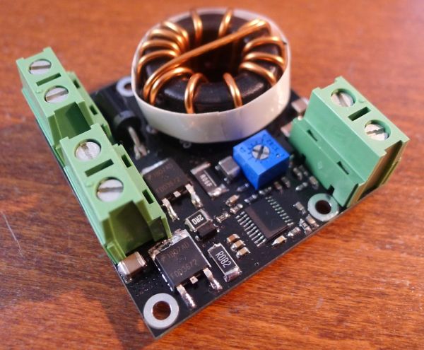
Current controlled boost LED driver and black soldermasks
By limpkin on Sunday, August 12 2012, 19:37 - My Projects - Permalink
Ok I agree, the two are not connected :-) ...

Unfortunately I can't reveal the schematics and production files this time :-( , as this board is some contractor work I've done for a company and also because it wouldn't be much use to you (it highly depends on your LED power requirements).
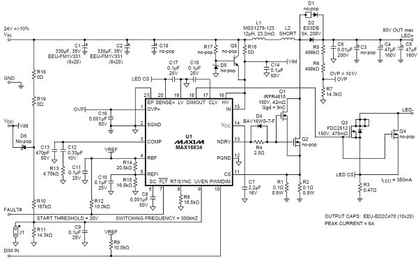
However I can tell you all you need to know to design your own LED driver based on the MAX16834 and also give you the design spreadsheets that are quite long to get.
The theory
First, if you don't already know it, a LED's brightness is controlled by the current going through it.
I know you're gonna tell me that voltage and current are related to each other, and you'd be right to do so. However, a LED intensity/voltage curve can be non linear and therefore better brightness adjustment can only be done by current control.
There are several ways to do current control and I'm not going to detail them here. The main difference between them is their efficiency.
For example, using a simple transistor is highly inefficient as it will dissipate the heat caused by the voltage drop * current going through it. Not important if you're driving a few LEDs, but very if you're driving 60W of LEDs.
Therefore, you need some way to adjust your LED string voltage depending on the current going through it in an highly efficient way.
That's just what a design based on a Boost converter does:
The MAX16834

The MAX16834 is a neat little chip (it's not the only one, there are plenty of others out there) that allows high efficiency designs for LED string driving.
It provides a platform for a Buck or Boost converter design, as well as brightness adjustment via analog/PWM input pins, as well as a fault output (in case of open/short circuits for example) and also diverse other functionalities that can be quite useful.
Using a resistor in series with your LED string, it will sense the current going through it and adapt the LED string voltage accordingly.
What you need to take care of

As my main goal is not to promote Maxim-ic components (even if you can get samples quite easily!), I'm gonna write a few advices for the design of this kind of electronics:
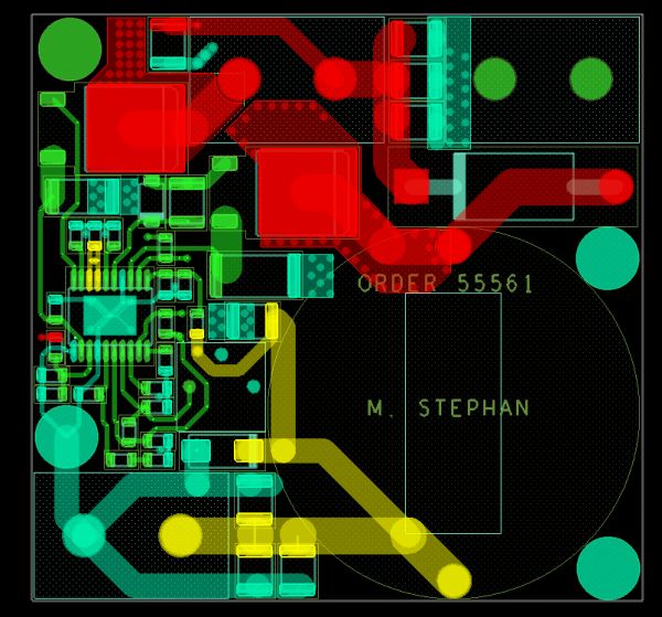
- be aware of the minimum required traces widths, which depend on the current going through them (duh...). You'll find a few calculators on the internet for it.
- create large copper areas on the top and bottom layers around the components that generate heat. Connect the two planes with a lot of vias (but not too many, that would compromise the PCB strength). Obviously, this advice is only valid if you use SMD components, which use the PCB as their heatsinks. The hot components are the 2 mosfets, the coil and diode
- if you're powering other circuits with the same power supply, be aware of the voltage ripple this circuit will introduce. This is caused by the boost switching frequency as well as the PWM's.
- get some cheap IR thermometer from ebay, that will allow you to check that all the temps are within the chips working range
- be aware that PCB temperature can affect components' characteristics (such as oscillators)
- with a scope, look how long it takes for the MAX16834 to attain stable current regulation by measuring rsense voltage. This will give you the maximum PWM frequency.
- directly measure the voltages with your oscilloscope probe. Don't forget that if you add wires for measurement, they will act as inductors, which is very annoying for fast rising signals such as the mosfet gate control.
- don't forget the MAX16834 heatpad (woups :-D ).
- protect your voltage input for transients with a TVS diode
- if you need an advanced input protection (such as reverse polarity protection), look at the LTC4365
The design spreadsheets & the final result

Here are two design spreadsheets (here and here) that I managed to obtain from Maxim. I personally used the excel sheet, as it seems it was the one used for the application notes.
For your information, I didn't have any bad surprises when assembling my first prototypes.
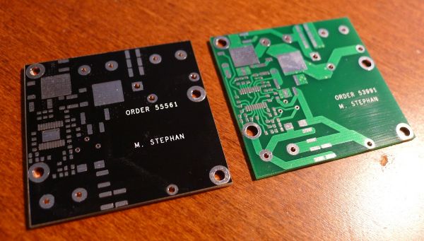
The black solder mask was just for fun... it feels like it is thicker than the conventional one, which makes the assembly process a bit trickier :-) .
It also hides all the PCB traces, so I would only recommend it once you are sure that your schematics are ok.
That's all for now! Not a lot of advanced information in this post, but at least I hope it gave you some ideas ;-) .

Comments
That's an odd looking toroidal inductor, with the wire going across the diameter on top. Is that just to get the leads to a desired position, or is it for current sensing or something like that?
@Bodger : Nope, that's just the way the inductor is :-)
@Bodger, IMO the top wire goes across the inductor, so that it gets soldered to the PCB on two opposite ends. Just for better stability - no glueing and it cant twist off.
@Polcmods : Yep! Sorry, I should have mentionned it
if you cant give us any plans for it do you intend to in the future or make this as a ready made unit?
@ejonesss : Yep, I'll release them in the future, but I really doubt they would be useful to you, as they are highly dependent on the LEDs used :-)
Hi,
Great write-up!
Any chance you could provide a rough estimate of the costs involved for production (BoM cost, PCB costs, etc.) in hobbyist quantities? (1-10)
Thanks,
Itamar
@int0x2e : Hi, thanks! Once again, it highly depends on your LEDs. The BoM of this particular boards costs 30$ for hobbyist qties, and has been made via seeedstudio fusion (so very cheap).
@Thomas Sarlandie : Nice project you have there! what's your current BoM cost? The only thing i'd say about your schematics is that you don't have an error output (in case of short/open circuits) :-)
@limpkin: great question ;) Right now the BOM is $37 in small quantity and $23 for 1000. This of course excludes the price of the LED which turns out to be by far the most expensive component.
I am trying to reduce that a little more by using a LT3476 (quad-channel controller) instead of 3 LT3518. Next version is being designed right now.
@Thomas Sarlandie : nice! good luck!
Have you gone any further with this design?
I'm interested as I'm looking for something similar to drive cree's XHP70s that I can do at home.
@Xenocatalyst : Unfortunately I have not!