High Voltage Power Supply for Nixie Tubes
By limpkin on Saturday, April 2 2016, 18:01 - My Projects - Permalink
It's always fun playing with dangerous voltages !
The Idea
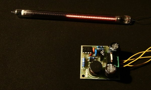
For quite a while I've had this project idea in the back of my head that would involve using many Nixie tubes.
These funny looking cold cathode displays were actually introduced during the 1950s and unfortunately need quite a high voltage to work (from 100V to 180V depending on the type). This meant that I had to find an easy, cheap and (if possible) not dangerous solution to power them.
IN-9 Tubes
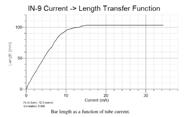
IN-9 tubes can easily be purchased on eBay and other similar websites. These tubes are current driven, which means that the length of the glowing bar will be proportional to the current fed to the display.
And as you can see from the graph above, the linearity is quite good between 0 and 8mA but not so much after that. Once the cathode is saturated at 103mm, feeding more current will increase the overall brightness... but the maximum recommended current is around 12mA!
This is a typical IN-9 voltage versus current graph:
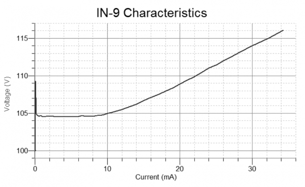
Using more than 50 of these tubes would therefore mean making a power supply capable of delivering up to 0.6A at 106V DC, which is a total of 64 Watts. As size isn't a problem, I turned to eBay again to find...
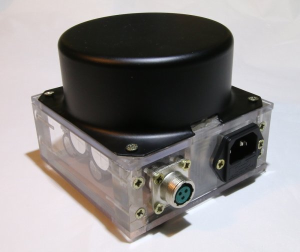
A Sealed 150W Toroidal Transformer !
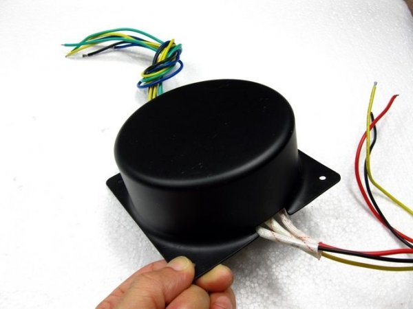
Isn't it pretty?
As this great webpage explains toroidal transformers have an excellent 90% to 95% efficiency, a good regulation and very low noise, which makes them a perfect solution to my problem.
The one I found has these specifications:
- Output voltage: AC24V-0-AC24V, 0-AC9V, 0-AC9V
- Input voltage: 0-110V-220V
- Size: 106x106x46mm
- Weight: 1.8kg (!)
Living in Europe, I just needed to connect the mains (through a fuse) to the 0/220V wires and I was good to go.
Getting More than 110V DC
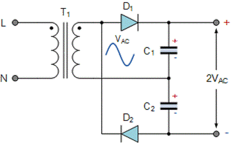
So if you've followed until here you might be wondering how we can generate at least 110V DC with a toroidal transformer that has 24V/0V/24V ouputs.
The first step is to use these 2x 24V outputs to get 48V AC, which is approximately 68V peak to peak as all AC voltage ratings are RMS. And with the full wave voltage doubler circuit shown above we then get 136V DC.
It is important to note that one consequence of using such a circuit is voltage ripple, as capacitors have to provide power when the 48V AC isn't at its peak voltage:
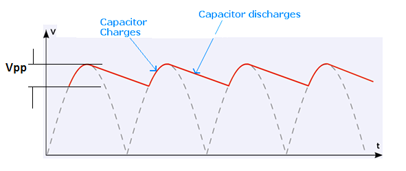
This ripple (on one capacitor only) can be computed using this formula: Vpp = A / F * C (A = load current, F = AC frequency, C = capacitance).
12V for the Main Electronics
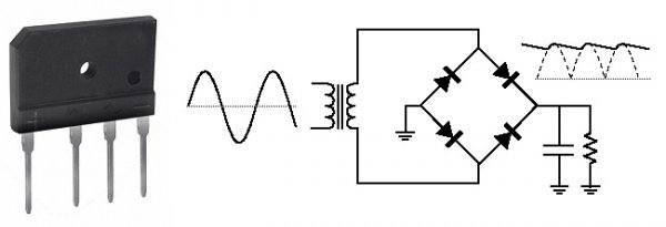
I'm sure you can guess that this future Nixie project will need another voltage than 136V.
I'm therefore using a bridge rectifier (or diode bridge) on the AC9V transformer output to get 9*1.414-(rectifier's diodes Vfwd*2) ~= 11VDC. This voltage will actually depend on how much current is drown, as the rectifier's diodes forward voltage changes with the current going through them.
It's interesting to notice that the voltage ripple on this 11V output will actually be A / 2 * F * C as the bridge rectifier (by definition) provides full-wave rectification.
Inrush Current & Selecting Fuses
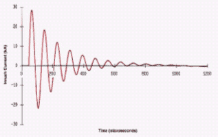
One should tread lightly when dealing with mains voltage. From this webpage:
When voltage is switched on to energize a transformer, the transformer core normally saturates. This results in a large inrush current which is greatest during the first half cycle (approximately .01 second) and becomes progressively less severe over the next several cycles (approximately 1 second) until the transformer reaches its normal magnetizing current.
To accommodate this inrush current, fuses are often selected which have time-current withstand values of at least 12 times transformer primary rated current for 0.1 second and 25 times for 0.01 second. Some small dry-type transformers may have substantially greater inrush currents.
For this 150VA transformer I therefore selected this 1A rated fuse.
However, during my initial tests I managed to blow one fuse and break one of the two SB5100 diodes used in the voltage doubler. I therefore guessed this was due to the massive inrush current going to each of the 3.3mF capacitors.
As the secondaries voltage may start at any state, this could potentially mean that ~70V is applied to a 3.3mF capacitor through a diode. I actually tried finding information that could help me find the maximum inrush current to the capacitors but wasn't successful due to several factors:
- no advanced specification of the toroidal transformer
- the fact that electrolytic capacitors' ESR will change depending on the frequency applied to them (at power-up high frequencies are present!)
- no advanced litterature on how a toroidal transformer behaves when a high capacitive load is applied to the secondaries (does it limit the secondaries current due to its construction?)
Anyway, I'm guessing some heavy maths are required to solve that one, so I just figured I'd just switch to using the massive 80EPF06 diodes, rated at 80A continuous and at 1000A peak...
CNC Milling Time !
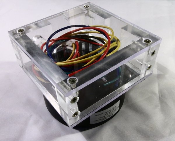
Unfortunately the hole in each corner of the transformer's base plate is not near the edges, which forced me to machine 5 & 15 mm acrylic sheets to make a nice box right under the transformer. As previously mentioned I've selected diodes & a rectifier bridge with very low forward voltages in order to minimize the heat that will have to be dissipated. As the box is closed (for the moment!) I'll be keeping a close eye on its temperature.
Gluing and Soldering Everything Together
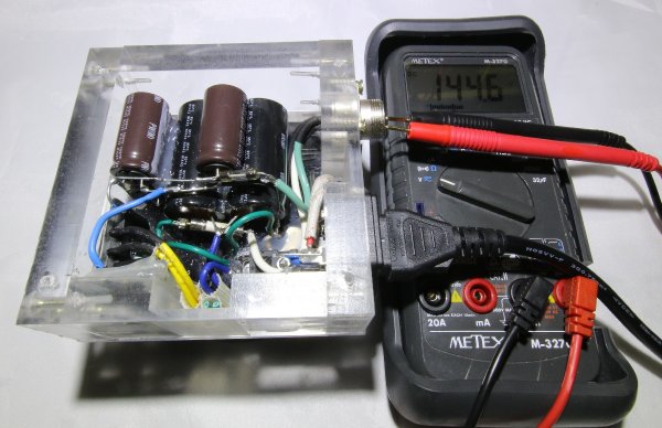
In the end, this is what I managed to fit in this homemade115x115x50mm box:
- 1x 430V surge absorber
- 3x 16V 8.2mF capacitors
- 2x 100V 3.3mF capacitors
- 1x rectifier bridge (for the 12V output)
- 2x 80EPF06 diodes (for the voltage doubler)
- 1x 400VDC 1A fuse for the 140V output
- 1x 125VDC 1A fuse for the 12V output
- 1x mains socket with integrated fuse slot
- 1x high voltage 3 pole high voltage socket
I also attached small aluminum plates to the diodes and rectifier bridge so they can help spread the heat to the case. As you can see in the above picture most components are held in place using hot glue.
Final Result

And here's what the final power transformer looks like!
As the capacitors can take a (very) long while to self-discharge, I'm thinking of adding a small mechanism to discharge them when the transformer is not powered. Anyway, stay tuned for the rest of this project!

Comments
I would connect the non-rectifying secondary terminal with a fairly high-value resistor: when it can trigger a set of zeners, short out the resistor with a relay, and use another to connect the load. If you get similar problems with the load, use a similar resistor there.
Hello,
You should add an LED on each of the output voltages. They will show you quickly that the fuses are OK and will be discharging the capacitors after input power is cut.
@GeekySeb : excellent idea!