An Open CVMeter
By limpkin on Monday, November 23 2015, 13:15 - My Projects - Permalink
Did you know that most ceramic capacitors lose up to 80% of their capacitance near their voltage ratings?
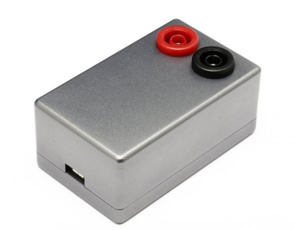
The Idea
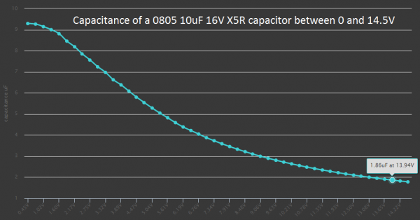
Not every electronics enthusiast knows that a ceramic capacitor's capacitance changes with the voltage you apply to it.
This can be particularly annoying when designing RC filters or DC/DC power supplies... you might therefore think your capacitor's value is 10uF when it actually is 1.8uF because of the way you're using it. Moreover, the graph displayed above isn't so easy to find in a capacitor's datasheet... and it sometimes simply isn't there.
That's why I made the OpenCVMeter, which aims to provide a Capacitance versus Voltage characterization accurate within 1% of the capacitors for your next project (or already have and are starting to wonder about right now...).
The Schematics
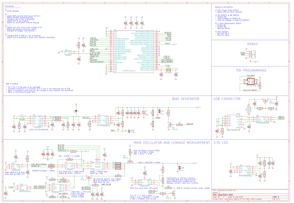
Don't try to read it all at once. Let's work block by block...
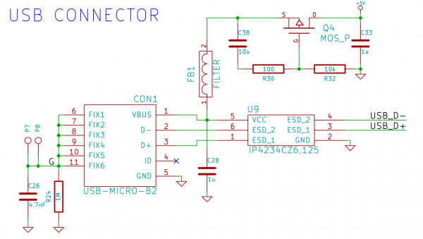
I preferred displaying the CV curve to the user through his/her computer rather than adding a small screen to the device. This obviously meant implementing a USB connection on the OpenCVMeter platform.
There are three main things you should notice in the above schematics.
- ESD protection is provided using the IP4234CZ6,125 (U9).
- The USB connector's chassis is electrically connected to the OpenCVMeter machined aluminum box and to the platform's ground through a 1M resistor and a 4.7nF capacitor. This has the main advantage of making a pseudo Farraday cage around the PCB and filtering out the noise on the cable shield connection. Moreover, it coincidentally is what Atmel recommends. You may read on all the different types of connections here.
- Lastly, the circuit made by Q4/C38/R30/R32 allows me to limit the inrush current after Q4. This is required by the USB specifications and you may read more about this particular topic here. In short, the inrush current shouldn't be above 100mA for too long when connecting your device. As you can guess, this was the case with the OpenCVMeter, so this circuit will gradually increase the 5V supply and limit the input current.
The inrush current that you can see below is therefore mostly due to C28:
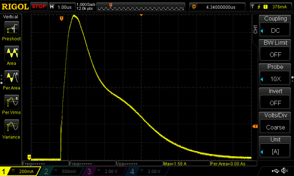
Looking closely at this capture you'll notice an inrush total of 12uC, which is below the 50uC maximum.
Bias Generator

Obviously the platform needed a controllable voltage generator. Here are the key elements of the above circuit:
- The Ultra-Low Noise, High PSRR, Low-Dropout Linear Regulator TPS7A4901 is used to lower a stepup-generated 16V to a desired voltage
- Output voltage control is achieved by varying VADJ between 0 and 1.2V, effectively changing the voltage that U5 sees through the FB pin and 'tricking' it to output a lower voltage.
- Generated voltage is measured through the 0.1% R22 and R23 resistors
- When disabling the voltage generator, C37's charge is dissipated through R37 by enabling Q5.
- When generating voltages under ~4.5V, the 16V is disabled and U5 is powered through D1, leading to less electrical noise in the platform.
I therefore had to design a small algorithm which allowed me to properly set the desired voltage by changing the voltage on VADJ... and it actually ended up being a bit more complex than I thought given the different loads that could be applied to the P3 output terminal.
Main Oscillator
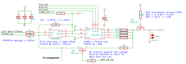
The role of each part in this circuit is:
- D4: ESD protection
- U2/U4/R13-16/R4/R5: RC oscillator
- Q3: limiting the voltage present at U4 to ~5V
- Q1: limiting the voltage present at U2 to ~3.3V
- R29: limiting the current when a voltage is applied to P2 (Q1/Q3 take a few us to limit the voltage)
The complete design was inspired by this article but contains major changes as a capacitor Equivalent Series Resistance (ESR) rendered the proposed circuit useless. Why? Let's first explain how the OpenCVMeter works.
As mentioned before, the OpenCVMeter is based around an RC oscillator. The R in the 'RC' is in our case a 0.1% precise resistor selected through U4 while C is the capacitor we want to measure. In theory, the oscillating frequency should therefore be directly related to the capacitor's capacitance:
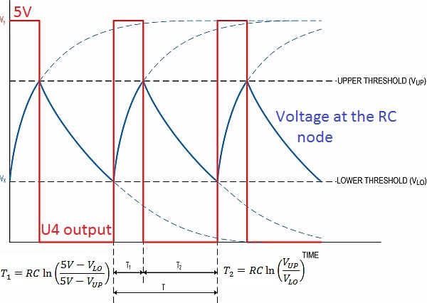
However, this is what the voltage at the RC node (on the P2 connector) really looks like:
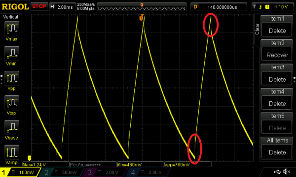
Notice how the voltage 'jumps' ? This is because of the capacitor ESR: when charging the capacitor, some voltage will be lost because of it. Hence, the RC oscillator frequency will depend on the capacitor's capacitance and its ESR. Not good.
The solution? Measuring the RC discharge time between two thresholds:

In this circuit U12 will therefore be at a high logic level whenever the RC node voltage is between AN_THRES1 and AN_THRES2:
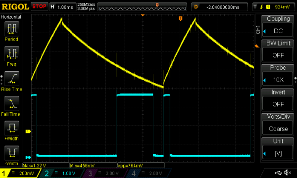
How do we know if the RC node voltage is rising or falling? Simply check the COMP_OUT output voltage level!
It is however important to note that the AND gate output may sometimes oscillate around transitions. This will be filtered out later. The two thresholds were set in such a way that even important ESR wouldn't impact the normal OpenCVMeter behavior.
Current Measurement
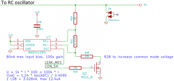
The OpenCVMeter can also measure leakage currents, this is the circuit in charge of it.
You might wonder why I didn't simply use a standard operational amplifier instead of a high-side current sense amplifier. This was mainly because of the N-Mosfet leakage currents and Vds voltage which would offset my measured current outside of my measurement range... I wanted to measure nA currents after all.
The Main Microcontroller
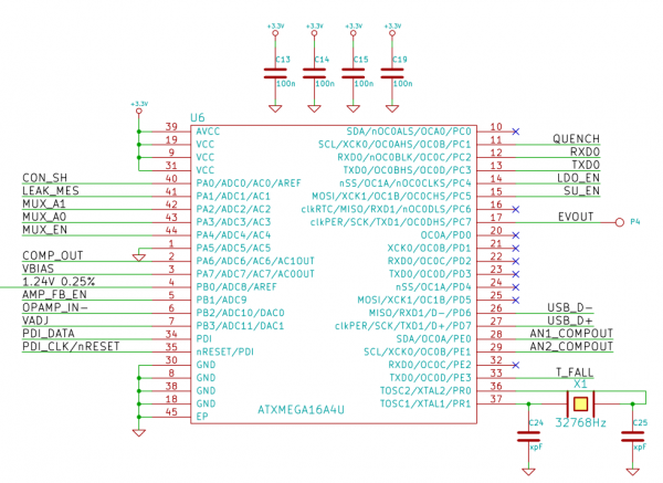
If you're still with me (congratulations!) you may remember that our chosen MCU should therefore have:
- an ADC: to measure the generated voltage
- a DAC: required to change the output bias voltage
- a USB transceiver: to send the measurements to the user's computer
- many IOs pins to drive the different circuits we have
The great ATXMega16A4U was therefore chosen for this purpose. Notable features are:
- Internal bootloader for easy reprogramming
- Internal 32MHz oscillator calibrated against an external 32KHz crystal
- 7 event lines, used to pseudo asynchronously measure the AND gate pulses
The Complex Bits I Left Out
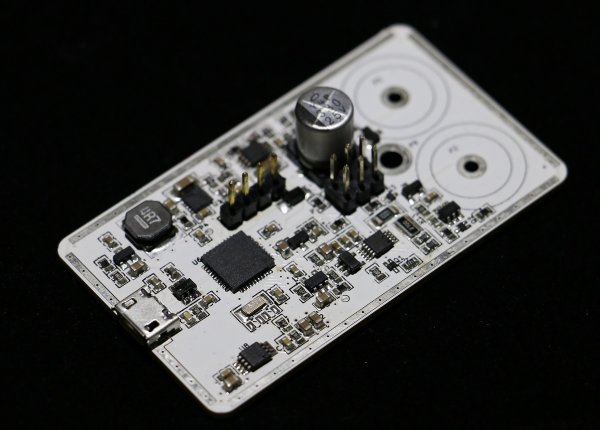
You may have noticed that I deliberately simplified or left out several things above as they were mainly related to calibration and getting precise measurements:
- very precise voltage references were used for our ADC & DAC
- AN_THRES1 & 2 can be precisely measured by injecting a voltage at OPAMPIN-
- the ATXMega16A4 ADC offset needs to be measured to get reliable measurments
- the ATXMega16A4 input digital filter is used to eliminate the AND gate oscillation glitches
- complete current measurement calibration may be done by placing a known resistor between P2 & P3
- all components around the RC oscillator were deliberately chosen to have a very low input capacitance
- when the OpenCVMeter terminals are shorted, Q3 Vds is equal to Vbias-5. Some power will be dissipated by it
Interested in an OpenCVMeter?

I just started a Kickstarter campaign for it.
Any support is appreciated, feel free to spread the OpenCVMeter word to your colleagues and friends!
In the meantime you may find most design files in the official GitHub repository and download the schematics (CERN licensed) here: schematics_v4.pdf. All hardware files will be released at the end of the kickstarter campaign.
I realized I actually didn't say much about the firmware, it only has 3k4 lines of code after all. It might however be interesting to you if you need a tiny HID stack made from scratch!

Comments
Thru-hole ceramic capacitors do not exhibit much dC/dV at all -- this effect is only prominent in small surface mount capacitors that are forced to employ goofy dielectrics with very high epsilon. So I don't agree that "most ceramic capacitors lose up to 80% of their capacitance". Only low voltage, high value (>1000pF), surface mount caps using screwball dielectric materials.
Is the BOM published anywhere? I didn't see it in the github project.
@Kris : I just pushed it to the repository.
Do you need a fancy Rigol scope to use this? Is that a USB host or slave connector? I would assume that this device is a slave but from the picture it looks like a host connector.
You don't really talk about the software side of it. My assumption when reading that you needed USB because you weren't putting a display on it was that the USB would be to connect it to a computer to act as the display.
Maybe you are connecting a USB storage device? Then plugging that into the scope to plot the data on it? Do those scopes do that? If so then I suppose it shouldn't be too hard to plug the stick into a computer for plotting if you don't have the scope.
I ask because I might be interested in the kickstarter but not if it requires an expensive scope that is outside my budget to use it.
It's a slave connector indeed. The device is detected as HID.