Easy-phi project: the template module
By limpkin on Wednesday, October 9 2013, 10:11 - My Projects - Permalink
Next in our Easy-phi descriptions: the template module.

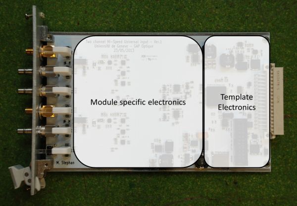
The template module consists of the core elements used by any easy-phi module. If you want to make your own module (we hope you do!), this is the starting point you'll need.

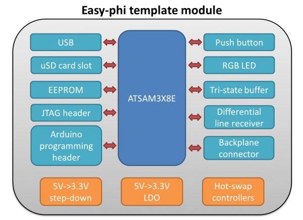
The main microcontroller is the ATSAM3X8E from Atmel, as it is one of the only uC having an USB Hi-speed transceiver (480Mbits/s). It also includes 512Kbytes of Flash and 96Kbytes of RAM. You may have guessed that it is the same microcontroller that Arduino uses for its Due, as we want Easy-phi modules to be Arduino compatible.
To program the module, there is a standard 20 pins 0.1" JTAG header and also another 8 pins 0.1" connector to flash the ATSAM3X using its embedded bootloader. The latter allows programming via the Arduino IDE.

A few words about the schematics. As you may know, 5V (0.5A) and 12V (4A) are provided by the backplane. The 5V is meant to power the template electronics only while the 12V is for the rest of the module.
To prevent an important current inrush when connecting a module, the MAX5824/25 are used. Not only do they provide a nice voltage rampup, but they'll also cut the power if the consumed current is above a defined value. In the template, the 3.3V used by the microcontroller is generated from the +5V by a step-down. An LDO regulator provides another (stable) 3.3V for the SAM3 ADC.
To use the 12V, a module has to make a request to the backplane. This is to make sure that we don't consume more power than the backplane power supply can provide if other modules are already connected and consuming power.

The few other components in the template are:
- one push button
- a microSD card connector
- one RGB led, to show the module status
- an i2c EEPROM, to store the module parameters and last settings
- a differential line receiver, to get the 10MHz backplane clock
- a tri-state buffer, to send and receive a synchronization signal
The last two components include a partial power-down feature. In case the data signals are connected before the power supplies, it will prevent the former from powering the rest of the circuit.
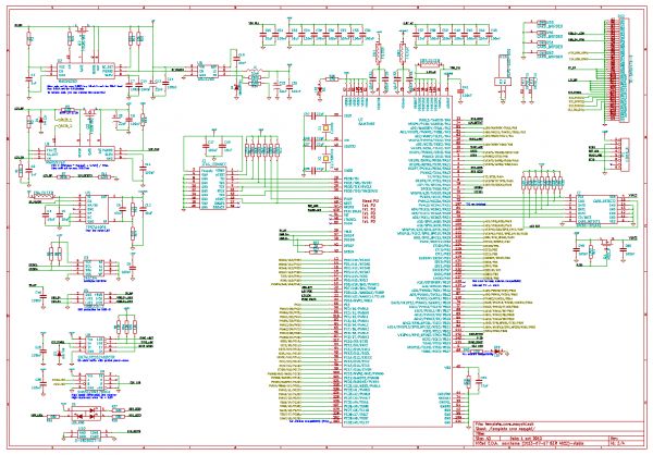
We really benefited from Kicad hierarchical design capabilities. The template schematics consist of one sheet containing the core components (that shouldn't be modified) and another with the top level design. In the top level sheet, all the microcontroller's unused pins are shown. The optional connectors, light pipes and RGB LEDs are also present.
To download the files, please visit the official website at www.easy-phi.ch
