XY Laser Scanner
By limpkin on Saturday, June 30 2007, 23:30 - My Projects - Permalink
Hey everyone!
This time I will present a project I made with 2 of my friends during 3 weeks at the end of my third year in my engineering school. I never thought I could work that much on a project: from 8h00 to 24h00 everyday...

All the pictures and files you will see are the ones taken at the time, nowadays I'm still working on it since some things doesn't work as well as before, due to several reasons I will explain later.
Well, let's start... Let me explain you the principle of a XY laser scanner. The concept is to deviate (quickly enough) a laser beam with two motorized mirrors in order to create a 'static' image on a wall (or anywhere else...). Well, there are no actual "motors", they are called galvanometers (or galvos). Once more, I will not really go into details but you are welcomed to contact me if you have any question (this blog is to explain the general idea and small details of each project, but you will find the reports we made at the end of this article). Basically, you have two types of galvos: open loop and closed loop. With closed loop galvos for each input voltage you have a corresponding angle as output, but they are generally slower than the open loop since a spring is located inside the galvo (with all its inconvenients...). For open loop galvos as the ones I used, a position detector is implemented on the axis so you have to create the appropriate feedback loop to attain the angle you want in a minimum time (yes, that is difficult...).
Firstly, let me show you the galvos I used: the General Scanning M2
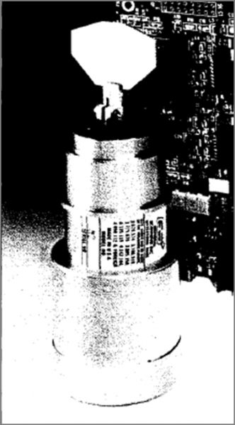
I found a block with two of them and their mirrors on ebay (for a change ;)), a 50mW green laser in China (I contacted several vendors...) and two adjustable mirrors to target the beam into the galvos' mirrors on ebay as well. Well, here is the picture of the whole box:
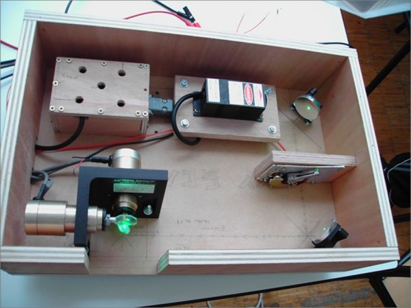
You can see on the top the green laser, on the right the two targeting mirrors and a small piece of hard drive used to cut the beam (actually, we used the HDD galvo), and on the bottom the two XY galvos with their mirrors. I let you imagine the beam path. Some things about this box: the laser has a blanking input that we shoud use instead of the HDD galvo. Actually we didn't have time to use neither the blanking input nor the HDD galvo (things to do when I'll have time...).
We wanted to create a fully autonomous system, so as I had been recently offered an ARM7 development board we chose to use it:
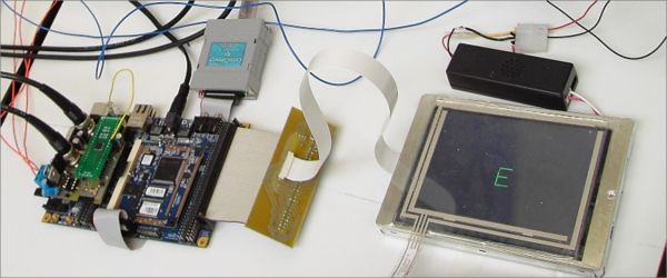
This board had an 70Mhz ARM7 microprocessor, if I remember well a 2mo RAM and 8mo FLASH. You can see on the left a small board I made for these project (more details later). I had interfaced a 12bits 320*240 pixels LCD screen (bought for 50$ on ebay as well) and a touchscreen. Originally, we wanted to create a tactile interface to select the shapes we wanted to display with the laser. Since we didn't have enough time, we were only displaying on the screen what we were currently displaying with the laser.
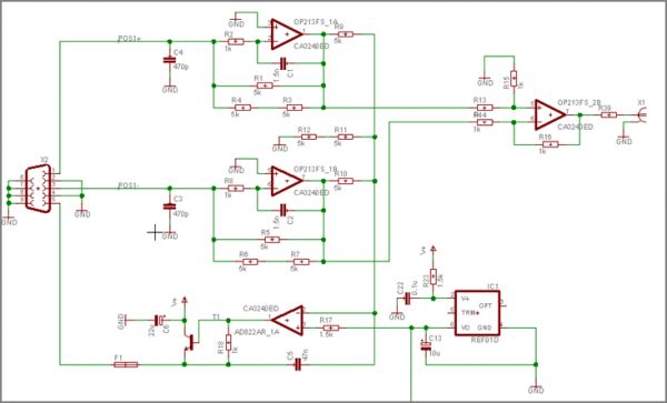
Well, let's start with the electronic parts. Firstly, as the output of the galvos' sensors was a current differential output, I had to make a board to properly convert it into voltage. That's where emailing General Scanning helped: they gave me the schematics to do that (since 1 optical degree is represented by a few uA difference on the sensor output and I wasn't sure of the pinout, I didn't want to take any risk...)
Now, we have to create the board that will be in charge of controling the galvos for a given command (in pratict a +10/-10 0V centered signal). The schematic was made based on a PID control loop general schema (Product - Integrator - Derivator). As before, I will not go into details here, there are very well documented web sites on the subject that will better explain what it is about, and it is also explained in the reports at the end of the article.

Here are the galvos control board along with the galvos sensors signal adjusting board:
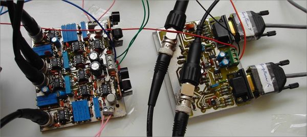
Using a waveform generator and by properly calibrating the control loop we could have this response curve for a square input:
Which was not very bad, I think that we were attaining a response time of 700Hz which is close to the announced 1000Hz objective.
To give the command to the control board, I interfaced a digital to analog converter on the ARM development board (that's the small board you saw on the third picture...). Here is a picture of the DAC outputing a triangle signal:
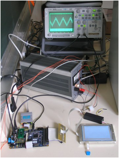
Once all the boards were operational and tested, we could connect them together and display the shapes we wanted. I won't talk much about the software part since my friend who did it lost all the source code (well, only the shape displaying part, as I had already a plateform to work on, from a previous internship made with this dev board). Originally, a program on the computer was taking as input a 3DS max shape, running some algorithms (djikstra, eulerian path...) on it to find the optimal path for the beam in a shortest possible time and then output the corresponding path so it could be used in our dev board. As it was a 3D shape, we were making it turn when displaying it...
The last picture is supposed to show a 3D "E". All the lines are not straight because our power supply wasn't powerful enough (a galvo is taking 4A peak...).
Now a few words about what I didn't have time to do and what I have done after the end of the project (the date was fixed by our professors, so the deadline was sharp...): we managed to have a turning "E" and the blanking part wasn't tested.
Since then, I made a box to put all the PCBs, the ARM dev board and the LCD in, bought two laptop power supplies (9A @ 19V) to power the whole system, BUT I have strange control loop output AND the DAC doesn't seem to work anymore... I suspect that I might have burned the voltage regulators and that some problems arise because I now have the appropriate power supplies... I will keep you posted on how it goes (I don't have much time these days).
Altogether, it was nice knowing that we could do such a project in 3 weeks only!
As always, here are the files we used/made (I'm sorry for the reports that are in french ;)):
eagle schematics and boards Galvos specs Project report (part 1 and 3) Project report (part 2) Project presentation
Additionnaly to these files, here is a part of the software platform I was talking about. Unfortunately I can't put all the .c files since some of the code was not made by me. Thus, you won't find in the archive the fonts, the graphics functions (lines, circles... even if I ported them) but I'm sure you'll find some interesting stuff (layers, animations, touchscreen handling...). This project was for the LH75401 logicpd development board and made using Crossworks produced by Rowley (I tried to contact the support for several things... but as a student I wasn't welcomed at all, they prefer talking to big companies so beware...)



Comments
Hi Limpkin,
Am Arul Manivannan, Doing second year in Engineering, South India.
-> Sir/madam, What are the types of Galvanometer (esp 2 axis mirror).available in the market.
-> Do a readymade kit (board and program kit) available in the market ? If so what name i should mention to purchase.
Your response is most considerable development for engineering curriculum Sir/madam, please help.
will you please leave your mail id ?
Thanks ! :)
Hello Arul,
Well I don't remember all the websites I've been on when searching for galvos... it really depends on what you're looking for. For professional use, you can check General Scanning or Cambridge technology websites.
Readymade kits are available on ebay, very cheap and I personaly think that they would be quite nice to work with (seach "galvo" on ebay.com).
Ps: I'm a guy ;)