A Mass Programming Bench for ATMega32u4 MCUs
By limpkin on Friday, January 13 2017, 14:54 - My Projects - Permalink
Or how to try to spend as little time as possible programming several thousands MCUs....
Why.... Just Why?
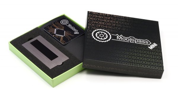
As you may know I started the Mooltipass offline password keeper project more than 2 years ago. Together with a team of volunteers from all over the globe I created two Mooltipass devices which were successfully crowdfunded through Indiegogo and Kickstarter, raising a total of around $290k.
Through a secure mechanism it is possible to upgrade the firmware running on the Mooltipass units. On our latest device, the Mooltipass Mini, we implemented signed firmware updates, which involved storing inside the microcontrollers' memory some cryptographic keys.
Here's the thing: instead of opting for a unique signing key for all our devices and have a single point of failure, we decided to assign a unique signing key per device. As you can guess, that meant unique Flash and EEPROM memory contents for every Mooltipass Mini out there. Moreover, it was anyway required as we also needed to store other unique information such as serial numbers and identifiers.
For the original Mooltipass, all unique information were programmed into the device using USB commands during the device functional test. That required trusting the product assembler and trusting that the machine running the functional test hadn't been tampered with during shipping.
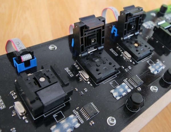
For the Mooltipass Mini we are doing things differently: we (or to be more precise, I) am programming the microcontrollers before our assembler solders them. Hence the 60x11cm PCB you see in the above picture: you can't do more than 60cm with 4 layers!
The Schematics
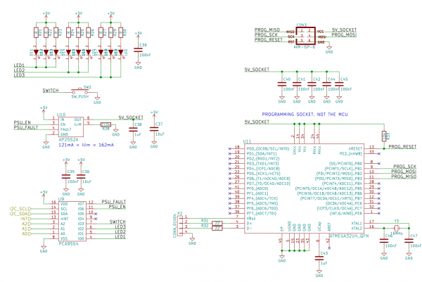
All the electronics revolve around the 9 programming sockets on the board. Why 9?
Because the required I2C GPIO expanders have a maximum of 8 configurable addresses and I still had standard GPIOs to use. Moreover, by orienting the sockets the way I did, 2 persons on one side of the board and 1 person on the other side can have easy access to 3 programming sockets each.
Each programming tile is therefore composed of :
- one 6 pin ISP connector
- one current-limited power switch
- one QFN44 programming socket
- one 16MHz crystal and its 2 load capacitors
- one button used by the user to start the programming process
- 3 LEDs rows: green / orange / red displaying the programming status
- one I2C GPIO expander to control these LEDs, power switch, button
Kicad hierarchical sheets were very convenient when designing the schematics: I only had to make a single sheet and duplicate it 7 times! Here is the top sheet:
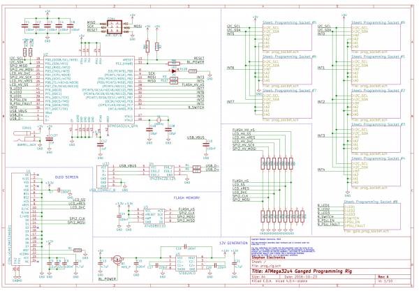
The very same microcontroller present in the Mooltipass Mini is controlling all the sockets. This allowed me to reuse most of the Mooltipass code, most importantly its USB stack and OLED display driver.
Bench Architecture
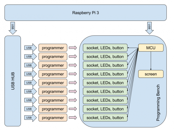
This brings us to the description of the complete programming bench architecture.
As shown in the above picture, an offline Raspberry Pi 3 is the brain of the complete system.
Using a USB hub, 9 ISP programmers (one for each socket) are connected to it, together with the USB enabled microcontroller controlling the LEDs, power switches, etc...
The program flow in the Raspberry Pi is fairly simple:
- through a USB command, query the main board MCU for pushed buttons
If a button is pushed
- generate a unique Flash and EEPROM file
- send a text to be displayed on the bench screen ("programming socket X with id Y")
- spawn a new thread containing a sequence of avrdude programming commands that will use these files
When programming is done
- display the result on the bench screen
- tell the bench MCU to light up the red or green LED row
- encrypt and store the unit signing keys in an external media
Everything was coded in Python, which allowed me to use threads, hex parsing libraries, encryption and data import/export functions. Yet it still took me several days to code as there was no room for mistakes.
Creating the bench MCU firmware was fairly quick as all that was added to the official Mooltipass firmware were the string display/button query/LED set USB commands. The cryptographic keys were generated using the random number generator running inside the bench MCU. It uses the jitter between the watch dog timer and the crystal as a source of randomness. This makes it a true random number generator.
Assembled Bench
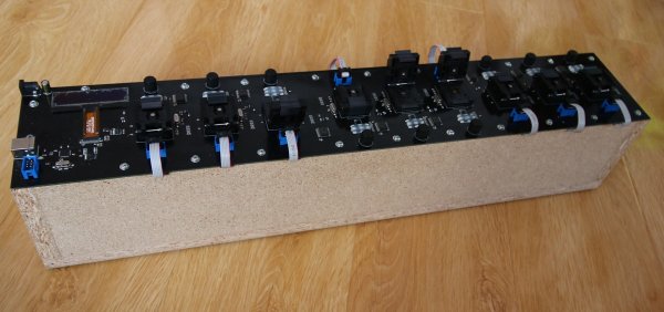
Making the box was fairly straight forward, as several holes were added to the PCB to screw it into place. The assembly made it in one piece to China!
As you can imagine all the programmers and the USB hub are under the PCB. If I had to do it again, I would add a second ISP connector under the PCB, though I'm not sure to have the space nor do I know if two programmers could coexist (as sometimes I directly plugged another programmer to it).
Choosing a programmer that could perform quick programming and be uniquely identified through a serial number turned out to be a pain as the Atmel AVRISP MKII isn't made anymore. I however found the Diamex ALL-AVR ISP Programmer which comes with a small tool allowing you to update it and program its serial number.
Adding the Costs
I hope that this article will give you some inspiration if you are to create your own mass programming bench.
This however won't be cheap, though still cheaper than professional ones:
- Board: $250
- USB hub: $20
- Programmers: ~$250
- Programming sockets: $90*9
- Raspberry Pi 3 with uSD: ~$50
- Electronic components : ~$100
- Helping wife when mass programming: several dinners
Excluding the dinners, this adds up to a total of $1500! You may find all the files for this project in this repository.
Cheers!

Comments
Nice work as usual. Very happy with my mini. Do you know when it will be possible to order mini? several friends waiting for it.
@Penoud : Thanks a lot! The mini will be available for purchase around beginning or middle of March. However, I'll have some stock in Switzerland at the end of January so don't hesitate to send me a private message if you want to purchase one.
I would build this up with a CNC machine (eg. shapeoko) picking up chipsets, placing them in the programmer and finally putting it back into a tray.
Placing so many chipsets by hand ... no way that I would touch more than 20 of them.
@Topbottom : That sounds great in theory, but in practise that wouldn't be so easy :)