Why you should never forget decoupling capacitors...
By limpkin on Friday, February 1 2013, 16:27 - My Projects - Permalink
A few words to explain how forgetting one decoupling cap could affect the rest of your system...

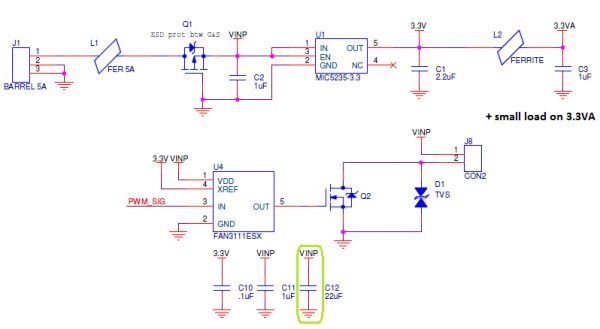
Please have a look at these simple schematics:
 Nothing really complicated here:
- you have your 12V voltage input from J1
- a ferrite L1 is placed to avoid high frequency parasites
- a mosfet P is present to avoid reversed polarity
- a low dropout regulator (LDO) U1 is connected to VINP to generate 3.3V
- a mosfet driver U4 is connected to VINP to drive the mosfet N Q2 to get sharp voltage changes on J8 (for better PWM)
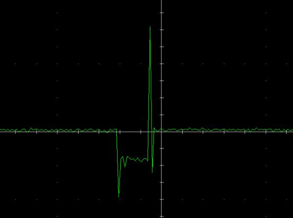
Let's remove the 22uF capacitor C12, connect a 2A load on J8, send a small pulse to the mosfet driver, and measure the voltage on VINP:
In this example, a 12V 2A AC/DC wall mount power supply is used.
Therefore, you can see that its regulation is far from optimal: you have huge overshoots when the load is applied and released.
Remember that a ferrite is just a lossy inductor. Therefore I'd have expected L1 to filter at least the positive rebound, but it seems it doesn't (maybe because in my case it is just a 80ohms ferrite).
Please note that I'm pretty sure the transient is actually bigger than measured as my oscilloscope is not the best.
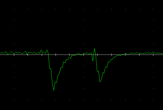
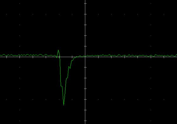
So guess the effect this will have on 3.3VA:
Yes... this is the perturbation you'd get on 3.3VA, even with the ferrite L2 and the decoupling capacitor C3.
I think it is quite useless to tell you that this is very annoying to have this kind of noise (0.6V!).
So why do we get this perturbation you ask?
Well, even if you are generating 3.3V from your 12V, your LDO is not fast enough to adjust its output when the transient occurs.
In a LDO datasheet, the parameter you'd want to look at is the Power Supply Rejection Ratio (PSRR), which depends on the perturbation frequency.
But even good LDOs won't be able to handle such fast transients.
One thing you could do is add another ferrite in series with the LDO, but i'm pretty sure you'd still have some perturbation.
In my case the AC/DC transformer has a small series resistance. If I use my lab power supply, the series resistance will be smaller and therefore the transient will be even bigger:
So what's the solution? Never forget decoupling capacitors.
If we put C12 back and place it close to Q2 and J8, when the transient occurs, C12 will provide the required high frequency current.
And tada! no more perturbation on 3.3VA ;-) .
Anyway, this example is for big loads, but you can guess that at smaller scales the effect is still the same.
Don't forget your IC's are actually made of tiny transistors that usually switch at the same time :-) .


