A Connected Lamp to Wake Me Up
By limpkin on Saturday, August 29 2015, 12:26 - My Projects - Permalink
I've always wanted to play with these 10W RGB LEDs!
The Idea
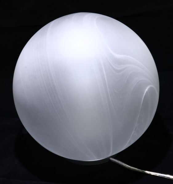
So for some reason I bought 2 IKEA lamps at a flea market. As IKEA furniture has a long history of being hacker-friendly, I figured they shouldn't be an exception to the rule.
My plan? Fit a few 10W RGB LEDs in there together with an ESP8266 to use the final result as an alarm clock.
The Schematics
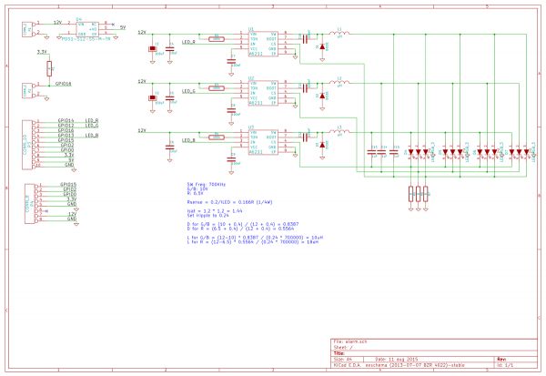
When you are dealing with a LED consuming that much current, you can't simply use a series resistor as the latter would need to dissipate R*I² in heat. I'm therefore using a dedicated LED driver that automatically adjusts the LED voltage to match a given current. As you can guess, it isn't much different than a standard step-down and just uses a shunt resistor to measure the current flowing through the LED.
The A6211 has an adjustable switching frequency set using R2/R3/R4 (to 700KHz in our case) and an EN input meant to be connected to a PWM signal. Its datasheet is well made so you can easily find all the information needed to select your passive components values. C13/C14/C15 are here to decrease the current ripple.
The complete board is 12V powered through P1. A DC/DC is placed on the board (I was lazy) to provide the 5V needed by my ESP8266 dev board. The P3 connector therefore serves as an interface beween the latter and our main PCB.
P4 is meant as an expansion connector to which will be connected an accelerometer. The goal is to hopefully measure REM sleep cycles to gradually increase the light at optimal times.
The great thing in this project is that the ESP8266 has all the required IOs for my purpose (PWM outputs, I2C, std IOs).
The Realization
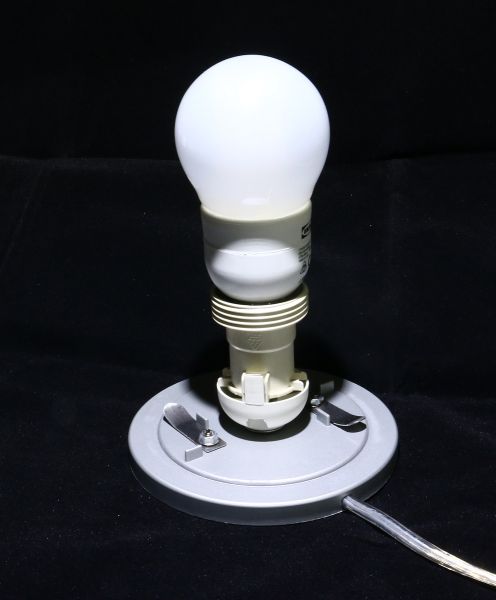
The inside of the lamp is fairly simple, I just needed to remove the socket to make room for my PCB:
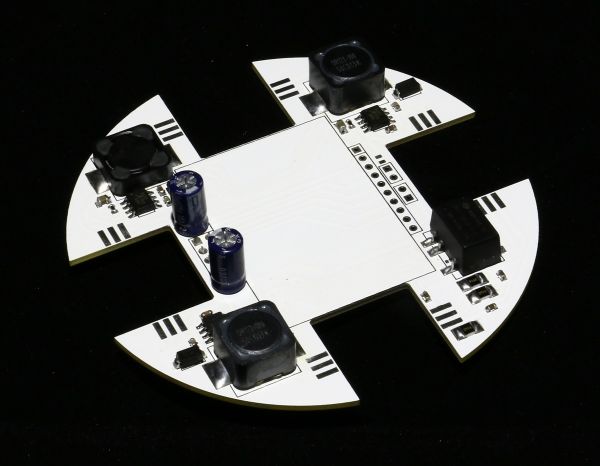
That was a fun PCB to design!
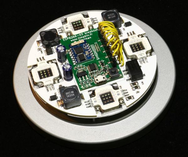
As you can see its outline is made at the right diameter and has slots in which will fit the RGB LEDs. The ESP8266 board will nicely fit in the middle. Keeping in mind that 10W LEDs don't have a 100% efficiency, I machined an aluminum plate that will be used for heat dissipation:
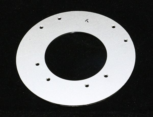
In this picture you can get an idea of the stackup:
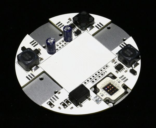
After applying some heat paste and soldering the LEDs:
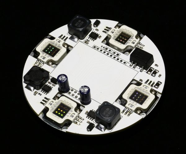
And this is what it looks like from below:
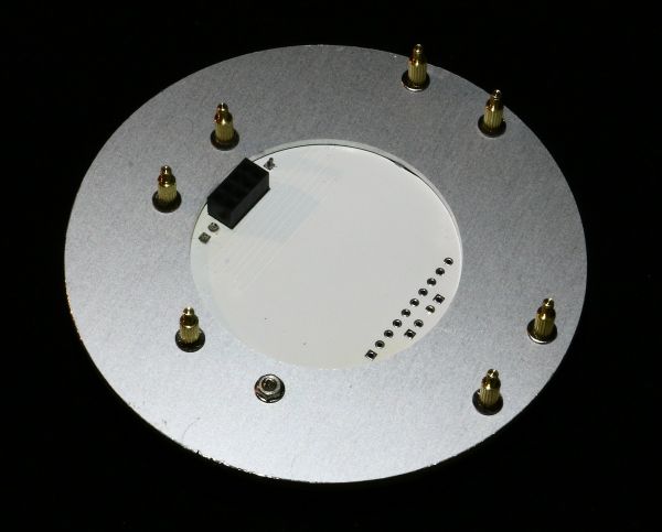
You can notice the M2x6mm brass standoff spacers and the power supply/expansion connector.
Here is the final result:

Obviously the USB port won't be used ;-) .
All Done!
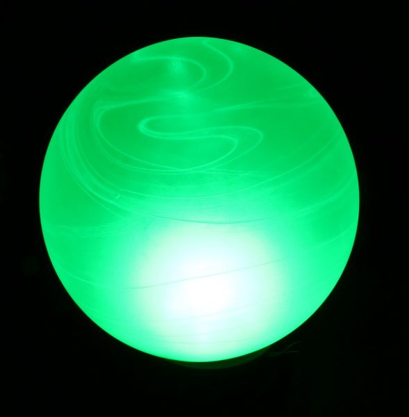
The hardware is tested (I've been blinded a few times!) and the software is still a work in progress but the core functionalities are there.
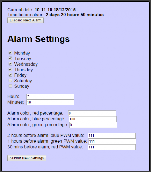
You may find all my files in this repository (HW part is CERN licensed). As you will see, all of the code is based on esphttpd with esp-open-sdk.
Cheers!

Comments
@Robert : thanks! I have not, mainly because the same function calls work on esphttpd but not on this solution with most of the code commented out. Could you by any chance run that code on one of your boards to make sure the problem comes from my side?
I second Robert. The two electrolytics are *definitely* too small for the >3A of ripple current they are seeing. Try patching some seriously large electrolytics into the circuit instead (like, 2*4700u low-ESR(!)) and see if it still reboots. You could also try giving the ESP8266 board an additional 470u or so on its low-voltage rail. To test this hypothesis, maybe try the software with an input voltage applied that is too low for the buck converters to work, but high enough for the ESP8266 board (say, 6V or thereabouts).
I like your PCB design!
Hi Limpkin,
I've read your post (via HAD) and see that you have an issue with your PWM init. Ive checked the forum where you posted this and see that till now you don't have an answer yet.
I've only looked into the schematic of your boosters and ESP and I have some comments that might help solving your problem. I assume you do not have an ossciloscope to measure all the signals and supply lines?
What I would recommend to do is place some series resistors in your controll lines from your ESP (all your GPIO's, use e.g. 10 or 20 ohm resistors). This tampers out some injected unwanted emi signals
Also buffer and decouple your 3V3 supply for the ESP. Place a bead and some decoupling capacitors (1uF 100nF, 10pF, with the smallest as close as possible to the ESP).
What I've also been missing is the decoupling at each A6211 input voltage booster (series bead or inductor and some capacitance).
Have you made a double sided PCB? Is your grounding made correct. Can your current (the one that needs to return to the source) make the shortest route or is your groundplane interrupted? You could send me a screenshot of the PCB layers.
Thats it for now, good luck finding the bug.
P.S. I see you are from France. If you are around in The Netherlands soon, drop by and we can do some measurments and debugging in my lab.
Hi Limpkin,
It's me again, right after placing my previous message and looking at the pictures one other thing crossed my mind.
Make all unused pins at the ESP defined at some level. You have now kept them floating so they are susceptable for EMI. Place a resitor(e.g. 100k or 10k) either to GND or to supply, so pull-up or pull-down the unused ones.
Best Regards,
Emiel
What value are the resistors for the LEDs? Maybe it shortens the power supply. Can you open the connection to the enable input of the amps and retry?
Wow! That's really great good work .
Regards
Steve
@jaseg : thanks for the kind words! Unfortunately the bug still happens when the esp8266 board isn't connected to the main PCB.
@Emiel : All the ESP IOs have 1k serial resistors. Unfortunately the bug still happens when the esp8266 board isn't connected to the main PCB. Thanks for the offer!
@recycler : Unfortunately the bug still happens when the esp8266 board isn't connected to the main PCB.... so it can't be a short circuit!
@RUSH PCB Ltd : thanks!
@limpkin :
Hi Limpkin,
Any further solving your problem?
Just for good practice on electronics:
I do not mean serial resitors in my last post. Any open input should be set at a defined value by either a pull-up or pull-down resistor. This makes your controller beter resistant against emi.
If you kept them floating any emi signal on that input could cause a voltage drop/current to flow and might change the level of the input.
Good luck,
Emiel
@Emiel : No news... still having this bug.