The whistled: how to remake a dozen years old project the right way
By limpkin on Friday, April 26 2013, 20:16 - My Projects - Permalink
Hey guys :-)
As the slightly changed adage goes: a video is worth a thousand words:
Interested? Have a look at my tindie page or click below to get more technical details...
So, why this project and why now?

I generally get project ideas before looking for components. For the whistled, things were the other way around.
A few months ago, when finding a new 32pins Cortex M4, I got plenty of ideas and the whistled was one of them.
As mentioned in the video, this tiny Kinetis K10 can perform around 80 [q15 2048 points] Fast Fourrier Transforms (FFTs) per second and still give me time to run my own algos.
This is explained by the fact that a Cortex M4 has a Digital Signal Processing (DSP) instruction set which is particularly useful for processing operations, and also because the ARM CMSIS library provides us with already optimized code to perform more complex functions such as FFTs.
As all the ground work was already done, I could actually focus on filter design and whistle recognition algorithms.
This took a lot of time and a lot of testing.
The specs and schematics
Let's start from the ground up:

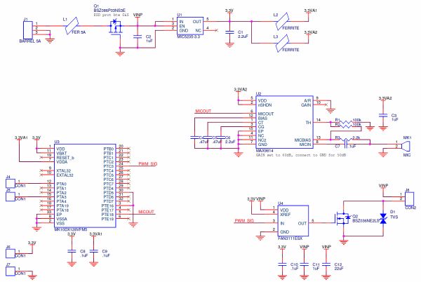
As you see, the schematics are fairly simple and I find it quite beautiful.
You'll notice:
- a few ferrites (L1/L2/L3) to filter the parasites that may be introduced in the system or made by Q2 switching
- a P-Mosfet (Q1) to prevent reversed polarity connections (I know you guys ;-) ).
- a standard 3.3V LDO (U1)
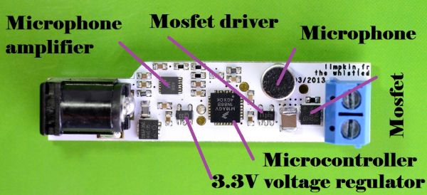
- our main Cortex M4 microcontroller (U3)
- a mosfet driver (U4) with its N-Mosfet (Q2) to allow proper dimming for big loads
- a microphone amplifier with Automatic Gain Control (AGC) (U2), which parameters were quite tricky to set
All the PCB traces you may touch are ESD protected: namely the power supply and the N-Mosfet drain, as all the rest of the PCB is covered by a transparent heat shrinkable tube. I really wanted to idiot proof my design (no offense intended).
Something worth noticing is that the Kinetis K10 has a 16bits timer with PWM outputs, resuling in a wide dimming range.
The platform will allow you to apply from 4.5V to 18V, with a max current of 5A at its input.
You could actually drive up to a 90 Watts load with this tiny 55x13mm board!
And of course, SWD pads are present on the board for you to flash your own program.
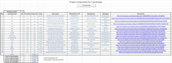
The Bill of Materials
Only click if you have a wide screen...

The BoM is not very cheap because of a few design choices:
- wanting to be flexible on the input voltage, leading me to choose more expensive components
- adding extra filtering (the ferrites)
- choosing terminal block connections
- choosing to protect the board from reversed polarity
- choosing low Rds mosfets to prevent the board from heating
I'd like to think that it is the cost of 'perfection', so the boards will work in every possible situation :-) .
The PCB

As you can see, everything is pretty much packed in there.
First prototypes were actually quite a pain to solder, the MAX9814's pins having a 0.4mm pitch.
For ESD protection I had to leave some clearing around the microphone, as the heat shrinkable tubing may not perfectly surround it. On the bottom layer, I also had to split the ground returns between the microcontroller/analog and power parts of the circuit, so the sound amplification may not be disturbed by the switching induced noise.

Final copper thickness is 60um which leads to a 7 degrees temperature rise at 5A for the high current trace.
Hacker-friendliness
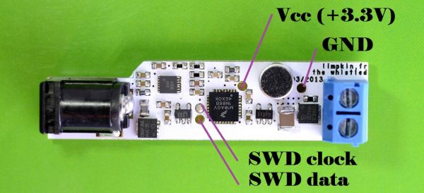
As already mentioned, the board is open hardware and has 4 pads for SWD connections (3.3V / 0V / clock / data):

So if you have some funky ideas for this platform, please knock yourself out.
This powerful cortex M4's processing capabilities will enable you to do more than just whistle recognition, and I am pretty sure a lot of these applications could involve party lighting ;-) .
You could also implement a "secret sound sequence" to open doors / safes.
The files

Here is everything you'll need to reproduce this work.
The schematics are fairly simple so you may want to make the PCB in the CAD software of your own choice.
When you'll work on the code, all you'll need to do is run your algorithms on the working_buffer variable in the run_recognition_algo function at the end of main.c
Whistle schematics Whistle gerbers Code template Datasheets User Manual
Update: and here are the complete source files!
The algorithm
Due to the number of comments I received, let me explain myself a bit more and also give you the general structure of the current implemented algorithm.
I managed to create a working algorithm but I do believe that some people may be able to make a better one. The algo I made is tied to this platform and more importantly tied to current implementation (two consecutive whistles to switch on/off) so I'm not sure it'd be of any use to those who want to tinker with the platform.
But if you really want to make the algorithm the same way I did, here is what it should do:
- detect two consecutive peaks in the FFT at different frequencies
- check the width of these peaks
- depending how you whistle, control the freq. deviation of the one peak
- check the isolation between the height of the peak and the nearby peaks
- tolerate one or two FFTs without peaks as your whistle seems continuous but actually isn't.
- only allow a whistling frequency range (8 to 46 in the current algo)
The algorithm I made prefers false positives (false detection) to false negatives (no detection when you whistle) as people whistle differently.
So it will actually be easier for you to tailor your code for your whistle rather than be as tolerant as me ;-) .
The final word
I really do believe in this project and that is why I took a shot and funded it myself .
This decision was pushed by lots of friends and colleagues that found the whistled easy to use and very convenient for their home automation setups. If this project is successful, I actually plan to make new families of product based on this principle. So if you are as motivated as me by this project, I'd really appreciate if you could have a look at my tindie page.
Cheers!

Comments
Really fun ;D
@bill : there's no reason you can't :)
Cool! Two questions though:
1) What about interference if you have these in adjacent rooms?
2) Can it tell the difference between a real whistle and a whistle on the TV? I could see the latter getting quite annoying... :)
This is really neat :) Have you considered calibrating it to birdsong, either to identify birds, or attract nearby species by completing the mating call? I'd buy one just for that.
@Decoherent : I haven't considered that actually. But in this case, it would be better to chose a Cortex M4 with a FPU (floating point unit) for more precision. Here the task is "relatively" simple and that's why a FPU isn't required.
@JM : Hi JM!
1) Doesn't happen if you put the whistled in a corner near the door (facing the inside of the room and not the room entrance)
2) Well, I noticed that most audio systems absolutely butcher the spectrum... so it doesn't happen. False positives may be caused by classical music and crappy mp3s/speakers that "regroup" nearby frequencies
@Jim : Hi Jim! I know what I'm gonna say is going to be quite hard to believe but here it goes. I actually am not sure that giving the "structure" of my algo is a good idea.
I think I managed to get the maximum performances of the current "shape" of the algo and I think it would be better that people design their own (without my influence) so they may create a better one. Let me know if I'm clear enough.
Basically what I want to say is that I'm not an expert at designing this kind of algorithm and I fear people may be biased to go "the easy way" and only fill the missing lines.
Redesigning an algo from scratch may actually lead to better performances.
Let me know what you think!
@Jim : You're right. I'll edit my blog post to include a few words about the algorithm then :). As you may have guessed the general principle is easy: just detect two consecutive narrow peaks. Good idea for the barking dog thingy btw.
@Adam and Jim: I just edited my blog post with additional details on the algorithm. If you want even more details, then I suggest we have a chat together to design an algorithm together
Anything whistling related really gets our vote, but we think you may have overcomplicated your algorithm. We did a whistle recognition algorithm and built it in to an iPhone game (called Extreme Sheepdog Trials). We based the algorithm on a simple zero crossing mechanism. It's able to match different whistles, and monitors changes in pitch, and works in the presence of significant background noise (in the App watch as the bar changes from red to green to see when it is recognised). No FFTs, a really simple algorithm.
Try the app for yourself, a free version is available, but we would obviously appreciate you going for the paid version if you like it!
@James : I actually find my algorithm too simple! Well as the CMSIS library was already here... it'd have been too bad not to use it :-) . Did you test for false positives with different kinds of music?
@limpkin : Any sine-wave sound will trigger it, so false positives can be created from certain musical instruments etc. And a real sheepdog whistle of course. But it does not suffer false positives from other noises such as more complex music.
To be honest, we were absolutely amazed how well our simple algorithm worked. It was only a couple of screens of code, and can recognise whistles in the presence of very loud background noise. And it can detect different types of whistle.
We were thinking of making a "find my Android phone" app where you could whistle and your phone would reply with a noise.
@James : neat! do you need high speed computations for your algo? I guess you must be quite reluctant to divulge some details :)
@limpkin : So our basic algorithm is below (we just made it up). I doubt it needs a very powerful processor to run it:
So if somebody told me that the above would work in the presence of lots of background noise, and that it didn't suffer false positives, I wouldn't have believed them. But it does work, and surprisingly well.
Try out the "Whistle Training" part of the game to see....
Really great project, and i just purchased one.
Have you experimented with hooking this up to an X10 or Insteon network to trigger more advanced commands?
@Brian : Thanks a lot! Well, I may try this for future versions actually :)
I've actually been working on an dimmable LED driver recently and would like to note something; specifically I'm trying to drive a 6ft/~2m string of LEDs. While PWM is a very easy way to dim the LEDs, when you have a ~12-30ft loop of wire with a pulsed signal travelling through it, you end up with a fantastic radio transmitter, especially if you're sending 1A+ of current down it.
I'm looking into making a constant current based design because of that. Just an FYI.
@Some Tinkerer : You make a very good point. This blog article might be what you are looking for then :-) .
Very cool. via DP
Great project! Great skills and cool project description!
I especially like the way you found a useful application from a micro+dsp.
Good luck for the IndieGoGo!
by the way, DangerousPrototypes did an article about the whistled : http://dangerousprototypes.com/2013...
best regards,
That's pretty cool. It made me think of a project that I have long considered. I would like to build a device that you could whistle a tune and it would convert it, on the fly, to a midi output. You could whistle like a piano, trumpet, etc.
Thank you for sharing your wonderful project with us.
@limpkin :
Floating point is not required as it does not buy you additional precision. The M4's DSP unit has a 32x32 + 64 Mac. You can be very precise. Floating point buys convenience for the the programmer and has little effect when design your algorithm for precision.
Fixed point is often a much better choice for audio and DSP as you can control the error over the entire numerical range (and it is a fixed error).
Couple that with the fact that the converter on that chip is effectively 12-bit in single ended mode, you simple don't need all that much precision. The SNR of an 16-bit Algorithm would be more than sufficient for this application.